|
|
| Fig. 2.3.1. Digidata 1200 Electrode Connections Help Box. |
Chapter 2 - GETTING
STARTED
If you are upgrading
from earlier versions of the LTP program, you will have write new *.pro protocol
files. The newer LTP24 program will not load protocol files you made using a
previous LTP program for reliability reasons.
Note that you can
analyze the same ADsweep files with LTP24 that were obtained with all earlier
versions of the LTP program.
2.2
Installing the LTP Program
2.2.1 Go
to the Explorer (in Windows 95/98) or File Manager (in Windows 3.x) and create
the folder \LTP24 on the appropriate drive (I will assume the C: drive for
this discussion). Then download the self-extracting zip file LTP24Z.EXE from
the 'LTP' program web site, www.ltp-program.com.
Then
double click on the LTP24Z.EXE file to extract the following files which
should now be in your \LTP24 folder:
| The
main LTP24 files: |
| ltp24.exe | the main LTP program | ||
| dos4gw.exe | the 32-bit DOS extender note that this version (2.01a, dated 3 April, 1996) is updated from the version used with LTP114J (version 1.97, 29 Feb. 1996). Delete the older version in \LTP114J. | ||
| ltpvga.fon | a font file required by the LTP program |
| Additional
files for using desktop icon for starting in reanalysis mode with Windows 95/98ME
and Windows NT/2000/XP: |
| Ltp24 Rean Win9598ME | to run the LTP Program in reanalysis mode on Windows 95, 98 or ME |
||
| Ltp24 Rean WinNT2000XP | to run the LTP Program in reanalysis on Windows NT, 2000 or XP | ||
| LtpReanal.ico |
the icon for LTP reanalysis |
2.2.2.
For Windows 95 or 98:
| Modify the autoexec.bat file in the C:\ root folder by using NOTEPAD.EXE or other text editor by adding C:\LTP24; to your PATH line like this: |
| PATH=C:\LTP24; |
Because
LTP24 uses a newer DOS4GW.EXE 32-bit DOS extender that can access 64 MB of RAM
memory (version 2.01a, April 3,
1996), and replaces the older DOS4GW.EXE supplied with LTP114J which can access
only 32 MB of RAM memory (version 1.97, Feb. 29, 1996), delete the older
DOS4GW.EXE in the \LTP114J folder. Also,
remove C:\LTP114J; from the PATH statement in the autoexec.bat.
To
implement the changes made to the autoexec.bat file you must first reboot the
computer by clicking on 'Start', then 'Shut Down', and then
'Restart the computer'.
2.2.3.
For MS-DOS 6.0/6.2 (with Windows 3.0/3.1/3.11):
| Modify the autoexec.bat file in the C:\ root folder by using EDIT.COM, NOTEPAD.EXE or other text editor by adding C:\LTP; to your PATH line like this: |
| PATH=C:\DOS;C:\WINDOWS;C:\LTP24; |
Because
LTP24 uses a newer DOS4GW.EXE 32-bit DOS extender that can access 64 MB of RAM
memory (version 2.01a, April 3,
1996), and replaces the older DOS4GW.EXE supplied with LTP114J which can access
only 32 MB of RAM memory (version 1.97, Feb. 29, 1996), delete the older
DOS4GW.EXE in the \LTP114J folder. Also,
remove C:\LTP114J; from the PATH statement in the autoexec.bat.
| If faster saving of data is required (forinstance for saving AD waveforms during fast 2Hz LTD stimulation) you may try removing the /X flag following SMARTDRV in the config.sys or autoexec.bat files located in the C:\ root folder. (This does not speed up saving on all computers. For example, this sped up saving AD sweep files faster on a Dell 486/66MHz, but not on a Dell Pentium/60 MHz.) In the config.sys file: |
| DEVICE =
C:\WINDOWS\SMARTDRV /X |
| becomes |
| DEVICE =
C:\WINDOWS\SMARTDRV |
| Or, in the autoexec.bat file: |
| C:\WINDOWS\SMARTDRV.EXE /X |
| becomes |
|
C:\WINDOWS\SMARTDRV.EXE |
To
implement the changes made to the config.sys and autoexec.bat files you must
first reboot the computer by pressing CTL-ALT-DEL, pressing the reboot button,
or by turning OFF then turning ON the power again.
2.2.4.
For Windows ME:
Same as for Windows 95/98.
2.2.5.
For Windows NT, 2000 or XP:
Same as for Windows 95/98.
2.2.6.
Check For Correct Memory Manager, HIMEM.SYS
If you are using DOS 6.x / Windows 3.x, you should have HIMEM.SYS is in your AUTOEXEC.BAT and not another memory manager like QEMM.SYS or 386MAX.SYS. The normal installation of DOS 6.x / Windows 3.x automatically installs HIMEM.SYS. Similarly, if you are using Windows 95/98 HIMEM.SYS does not have to be in your AUTOEXEC.BAT - it automatically used. However, you should make sure that another memory manager like QEMM.SYS or 386MAX.SYS is not in your AUTOEXEC.BAT. (It is possible that other memory managers such has QEMM.SYS, 386MAX.SYS may work fine, but I have not tried them and therefore will not recommend them. Only use them if you are 100% sure they are working correctly.)
The reason for being careful about what memory manager to use is the following. The LTP24 program uses a DPMI (DOS Protected Mode Interface) host which helps the LTP program talk to the computer hardware. If the HIMEM.SYS memory manager is used with the LTP program, then the DPMI host is the Watcom C / Tenberry's DOS/4GW DPMI host. This is a well defined DPMI host which works well in real-time, and has been well tested by me.
DPMI hosts can be either 'real' or 'virtual'. When the DPMI host is 'real', the DOS program has complete control of the machine. When HIMEM.SYS and Watcom C / Tenberry's DOS/4GW are used, the DPMI host is 'real', and when the LTP24 program blocks keyboard, disk drive, or network card interrupts during data acquisition and stimulation, they are really blocked and there are no delays!!!!
Some DPMI hosts can be 'virtual' DPMI hosts meaning that the DOS program does not have complete control of the machine. With a 'virtual' DPMI host, the keyboard and disk drive interrupts appear blocked to the DOS LTP24 program but they are not actually blocked in the computer - and therefore substantial delays of 1 msec or longer can occur during acquisition/stimulation and your synaptic potential would appear much shorter.
Therefore, be sure you are using HIMEM.SYS, and test for any delays during the data acquisition / stimulation sweep by using a triangular waveform input (as described in Section 2.9.1). Also test the sample-to-sample jitter by measuring the width of a train S0 pulse using an oscilloscope (see Section 2.9.2).
2.3 Installing the
Data Acquisition Board
The LTP24 program presently runs on four data acquisition boards: the Axon Instruments Digidata 1200 board, the Scientific Solutions Labmaster board, the Pico Technology 42-ADC board, and Measurement Computing's CIO-DAS08/JR-AO.
2.3.1 Axon Instruments Digidata 1200 Board
The Digidata 1200 board is one of the most popular data acquisition boards for neurophysiology, almost solely due to its use by the Axon Instruments program pClamp. However, Axon Instruments no longer sells the Digidata 1200.
The Digidata 1200 board comes with its own interface. LTP24 uses two analog input channel AnalogIn0 and AnalogIn1, two analog output channels AnalogOut0 and AnalogOut1, and four digital output channels DigitalOut0, DigitalOut1, DigitalOut2, and DigitalOut3. Note that there is only up to 1 bit AD channel crosstalk for a -10 to +10 volt input into the other AD channel. AD channel crosstalk is not a problem with the Digidata 1200 board.
| The factory settings for the Digidata 1200 board base address (320 hexadecimal) will normally be used. If so, the LTP program will be started by the command line: |
| C:\YOURDATA\010704\> ltp24 |
| However, if you need to use the Digidata 1200 board at a non-default base address, enter the following command line (for example at a base address of 100 hexadecimal): |
| C:\YOURDATA\010704\> ltp24 100 |
| For an LTP experiment with one or two recording electrodes (extracellular and/or intracellular), intracellular (IC) stimulation through one recording electrode (if applicable) and two extracellular stimulating electrodes (S0 and S1), connect the recording electrode amplifier and Stimulation Isolation Units (SIUs) as shown in the Digidata Electrode Connections Help Box (Fig. 2.3.1). This information can be viewed in the LTP program by using the menu command: |
| Help -> Electrode<->AD board Connections |
|
|
| Fig. 2.3.1. Digidata 1200 Electrode Connections Help Box. |
Presently, the Digidata 1200 board is programmed using the slower Software controlled acquisition and stimulation, and therefore does not run on some of the slowest computers (e.g. a Tandon 16 MHz 386) but does work on faster computers (e.g. a Tandon 25 MHz 486 and above). With Software controlled acquisition there is also some Analog input and Analog/Digital output sample-to-sample jitter on the order of 2-7 usec. For timing errors in sample-to-sample jitter and sweep-to-sweep jitter with the Digidata 1200 board, see APPENDIX B.4 and APPENDIX B.6, respectively.
2.3.2 Scientific Solutions Labmaster Board
The Scientific Solutions Labmaster data acquisition board in the past been one of the most commonly used AD boards in neurophysiology, again due in part to its use by the Axon Instruments program pClamp. The Scientific Solutions Labmaster board was also previously marketed by Axon Instruments, and Axon Instruments also previously sold their own interface unit for the Labmaster board, the Axon Instruments TL-1 interface. Scientific Solutions still sells the Labmaster board, although Axon Instruments does not.
Note that the Labmaster board has 2-3 bits AD channel crosstalk. In general, I think that the Labmaster board is very good for 1 AD channel recording (AD channel crosstalk is not an issue). However, the board is just acceptable for 2 AD channel recording, because of the 2-3 bit AD channel crosstalk, although I think this crosstalk is low enough to live with. However, if you are doing 2 AD channel recording, it is best to use a Digidata 1200 board because there is only up to 1 bit AD channel crosstalk.
2.3.2.1 Program Startup and Connections for the Labmaster Board
The electrode <-> interface connections for the LTP program are based on this TL-1 interface. LTP24 uses two analog input channels (physical AD channel AD15 for logical AD channel AD0, physical channel AD14 for logical channel AD1), two analog output channels DA0 and DA1, and four digital output channels C4, C5, C6 and C7. The input channels (AD15 and 14), and the output channels (DA0, DA1, Ports C4, C5, C6 and C7) are those commonly used by the Axon Instruments program pClamp 6, and the LTP24 program will automatically work on a computer set up to use pClamp 6.
| Because the LTP24 program cannot automatically detect if a Labmaster board is installed (as it can do for a Digidata 1200 board), an additional word 'labmaster' must be added to the command line when LTP24 is started in order to use the Labmaster board. The factory settings for the Labmaster board base address (710 hexadecimal) will normally be used. If so, the LTP program will be started by the command line: |
| C:\YOURDATA\010704\> ltp24 labmaster |
| However, if you need to use the Labmaster board at a non-default base address, enter the following command line (for example at a base address of 100 hexadecimal): |
| C:\YOURDATA\010704\> ltp24 labmaster 100 |
| For an LTP experiment with one or two recording electrodes (extracellular and/or intracellular), intracellular (IC) stimulation through one recording electrode (if applicable) and two extracellular stimulating electrodes (S0 and S1), connect the recording electrode amplifier and SIUs to the Axon TL-1 interface as shown in the Labmaster Electrode Connections Help Box (Fig. 2.3.2). This information can be viewed in the LTP program by using the menu command: |
| Help -> Electrode<->AD board Connections |
 |
| Fig. 2.3.2. Labmaster Electrode Connections Help Box. |
For timing errors in Analog input and Analog/Digital output sample-to-sample jitter (on the order of 2-4 usec) and sweep-to-sweep jitter with the Labmaster board, see APPENDIX B.4 and APPENDIX B.6, respectively.
2.3.2.2 Measurable AD Channel Crosstalk in the Labmaster board
The Labmaster board is a small, but measurable, amount of crosstalk between the 2 AD channels. Note, however, that AD channel crosstalk is NOT a problem when using just 1 AD channel.
If -10 to +10 volts is input into one AD channel, then a 2-3 bit negative shift occurs in the other AD channel Because the 12 bit AD converter in the Labmaster has 4096 different levels or 'bits' over the -10 to +10 volt range, the AD channel crosstalk is ~ 3/4000 or ~ 0.075%. Furthermore, the amount of crosstalk is roughly proportional to the negative input voltage into one AD channel, such that -5 volts input into one AD channel causes only a half the bit shift in the other AD channel.
The AD crosstalk is up to 1 bit in the Digidata 1200 board, and 1-4 bits in the DAS08/JR board.
However, Labmaster boards can be slightly different, so be sure to measure the amount of crosstalk between the two AD channels for your Labmaster board (see Section 2.9.3 and also APPENDIX B11).
If you are amplifying well above the 'bit' level, this should not be a problem. In other words, if the EPSP or other signal you are measuring is say 400 levels or bits in amplitude (approximately 1/10th of the full scale of 4096 bits), then a 3 bit shift (caused by the other AD channel going from -10 to +10 volts) would cause a 3/400 or 0.75% error in amplitude measurement. For example, when measuring extracellular EPSPs, if your AD0 Gain is x1000 and you are recording 4096 different levels over the -10 to +10 volt input range, this means you effectively have ~ 4000 levels or bits in a 20 mV range. Therefore, a signal of 400 levels or bits would be 1/10th of 20mV, or 2 mV. Therefore, for 0.75% error of the EPSP peak measurement, the EPSP amplitude should be at least 2 mV.
If you think this amount of crosstalk is too large, either increase the gain of the AD channel you are measuring from, or use a different board such as the Digidata 1200.
Feel free to contact support@winltp.com if you do not understand this and want to use 2 AD channels on this board.
2.3.3 Pico Technology's ADC-42 Board
I wanted to have the LTP program also work with a low cost data acquisition board. At present, the cost an AD board can be twice the cost of a completely adequate Pentium computer. The Pico ADC-42 board is a very low cost (ca. £100 / $150) 12-bit AD 'board'.
However, in LTP24 I installed another inexpensive board, Measurement Computing's CIO-DAS08/JR-AO that fits into an ISA slot, uses 2 AD channels and has two analog outputs. Although the Pico board is very good (especially with the added Software Calibration), the DAS08/JR board can be easier to install than the Pico board (sorting out the parallel ports can be a problem), it has two analog outputs (versus none on the Pico board), it is very good for 1 AD channel recording, and it is acceptable for 2 AD channel recording (as long as AD channel crosstalk is considered). Therefore, in general I think that the DAS08/JR board is better than the Pico board.
Nevertheless, the Pico board continues to be useful because it has been found to acquire data on at least some recent PCI only bus desktop computers (such as the Dell 8200 1.8GHz P4 computer). The Pico board has an accuracy of +1% which is adequate for extracellular experiments, but in LTP24 I added Software Calibration making it accurate enough for intracellular and patch-clamp recording.
2.3.3.1 Program startup for the Pico board
The Pico ADC-42 'board' plugs into a parallel printer port and acquires data on one AD channel. Digital output can either come from the same printer port or a second printer port (which can be separately purchased for ca. £10). Sometimes the second printer port is necessary because they often have greater digital current output which may be necessary for triggering some SIUs.
|
If you are using the Pico board, it is good to put these commands into a batch file (say LTP.BAT) in the C:\LTP24 directory, and always call the LTP24 program from the batch file.
2.3.3.2 Connections for the Pico board and Printer Port
| For an LTP experiment with one recording electrode (extracellular or intracellular), intracellular (IC) stimulation through the recording electrode (if applicable) and two extracellular stimulating electrodes (S0 and S1), connect the recording electrode amplifier and SIUs to Pico42 board on LPT1 and digital output through LTP1 as shown in the Pico ADC-42 / One Port Electrode Connections Help Box (Fig. 2.3.3.2.1). This information can be viewed in the LTP program by using the menu command: |
| Help -> Electrode<->AD board Connections |
 |
| Fig. 2.3.3.2.1 Pico42 Electrode Connections Help Box (using one printer port). |
Use Pin 18 (chassis Ground) if you want to ground coaxial shielding. The wire connections are shown schematically in Fig. 2.3.3.2.2, and a picture of the Pico-42 ADC board and digital output using the LPT1 parallel port on a laptop computer is shown in Fig. 2.3.3.2.3.
|
|
| Fig. 2.3.3.2.2. Ribbon cable connections for Pico board and Digital Output for connection to one parallel port. |
 |
| Fig. 2.3.3.2.3. Photo of the Pico ADC-42 connected to the parallel port of a laptop computer by a ribbon cable and two DB-25 plugs. The parallel port also produces four digital outputs (Right to Left - Green/Right plug, Wire 1, DigitalOut0; Yellow plug, Wire 2, S0; Red plug, Wire 6, S1; White plug, Wire 8, IC) and a ground to the parallel port (Black/Left plug, Wire 10, GND). |
For an LTP experiment with the Pico ADC-42 board connected to LPT1 and digital output through LPT2, connect the electrodes as shown in the Pico42 / Two Port Electrode Connections Help Box (Fig. 2.3.3.4).
|
|
| Fig. 2.3.3.2.4. Pico ADC-42 Electrode Connections Help Box (using two printer ports). |
Use Pin 18 (chassis Ground) if you want to ground coaxial shielding. The wire connections are shown schematically in Fig. 2.3.3.5 for the connections of the digital output from the second of two parallel ports.
|
|
| Fig. 2.3.3.2.5. Ribbon cable connections for the Digital Output from the second of two parallel ports. |
There are two potential problems with the Pico ADC-42 board. First, is your computer fast enough? When the LTP program is started it will automatically determine if the computer is too slow for the Pico board, (for example by running ltp24 pico42_dio_1 as described above). If the computer is too slow, the program will terminate (see APPENDIX B.10). You can even test this without the Pico board being installed. This is because the speed of the acquisition is determined by how fast the data can be read from the parallel port (one bit at a time!), and the Pico board does not actually have to be installed to do this. Pico board AD conversion is always complete within 100 usec.
The second potential problem with using the Pico ADC-42 board is: Are the parallel port digital outputs capable of triggering a SIU? We've found that LPT1 has difficulty triggering our Neurolog SIUs, but LPT2 output will trigger them. Again you can test this digital output capability without having to have the Pico board installed.
If you want to use the Pico board with the LPT1 parallel port and it does not have enough current output to trigger your SIUs, you could interface to a TTL chip for amplification. Alternatively, you could use four 4.7 Kohm pull-up resistors connected to a 5 volt source - read the Web document "Interfacing the Parallel Port" at www.senet.com.au/~cpeacock/parallel.htm#2 - although like they say, you do so at your own risk.
Finally, according to the Pico Technology, the accuracy of the Pico ADC-42 board is about +1%. Because of this we presently use the Pico ADC-42 board only for extracellular LTP experiments, although, if you calibrated your system and you were sure the board was within your accuracy requirements, you could use the board for intracellular recording and patch clamping.
Also note that the input voltage range on the Pico board is -5 to +5 volts (in contrast to the -10 to 10 volts on the Labmaster and Digidata 1200 board). For timing errors in Analog input and Digital output sample-to-sample jitter (on the order of 2-5 usec) and sweep-to-sweep jitter with the Pico board and printer port, see APPENDIX B.4 and APPENDIX B.6, respectively.
Finally, note that the fastest the Pico board can do repeat ADsweep (LTD) stimulation is 1.0 Hz (see APPENDIX B.5).
| Pico Technology can be located on the Internet: |
| www.picotech.com |
2.3.3.3 Software Calibration of analog input to the Pico board
According to the Pico Technology specifications on the ADC-42 board, the inaccuracy +1%. In LTP24 I have added software offset and gain calibration that is applied to the sweep data just after the sweep is obtained. For the acquired data, this adjustment is made at the 16 bit level even though the board has only 12 bits accuracy, so this ensures monotonicity.
|
Considerations about using Software Calibration of the input signal |
|
If you are performing extracellular experiments: |
| a) | A slight offset error should not make any difference, so don't bother adjusting the offset. | ||
| b) | The +1% gain error at full scale is probably not important, particularly if you are comparing EPSP slopes to % of control. But if it is, you can adjust it using an accurate and calibrated multimeter of at least 4 and 1/2 digits precision. |
|
If you are performing intracellular voltage or patch clamp experiments: |
| a) |
An offset error may well be important, particularly for signals near 0 volts, and the offset can easily be adjusted |
||
| b) | The +1% gain error at full scale may well be important. If it is, you can adjust it using an accurate and calibrated multimeter of at least 4 and 1/2 digit precision. The AD board is more accurate than the more common 3 and 1/2 digit multimeters, so using one of these is pointless. |
WARNING: This software calibration is specific to each Pico board. If a new Pico board is installed it must be calibrated anew.
Enabling the software calibration
When the LTP24 program starts up, the Pico offset and gain adjustment fields cannot be altered (for protection against inadvertent changing). However, in the Options menu that appears when a Pico board is being used, picking Enable Pico42 offset/gain adjust (Fig. 2.3.3.3.1) enables offset and gain adjustment fields for the Pico board to appear in the Miscellaneous page (Fig. 2.3.3.3.2). Thus the AD0 Offset Adjust field and the AD0 Gain Adjust field can now be changed.
|
|
| Fig. 2.3.3.3.1. The Options menu that appears when a Pico board is being used that enables offset and gain adjustment fields to appear in the Miscellaneous page. |
|
|
| Fig. 2.3.3.3.2. Miscellaneous page when the Pico board is running. The AD0 Offset Adjust and the AD0 Gain Adjust fields can be modified. |
Once the Offset and Gain Adjust fields have been edited they can be 'locked' in place and uneditable by using the Options menu and choosing Disable Pico offset/gain adjust (Fig. 2.3.3.3.3). |
|
|
| Fig. 2.3.3.3.3. The Options menu that appears when a Pico board is being used that makes the offset and gain adjustment fields in the Miscellaneous page uneditable. |
Software Calibration Proceedure
Note: It is important to perform offset adjustment before gain adjustment.
Analog input adjustment: |
| 1. | First, adjust analog input offset by grounding out the input (connect AD0 to AnalogGround, eg the BNC shield) and then use the direct signal measurement at high gain to put in a few bits to the AD0 Offset Adjust field. Because adjustment is at the 16 bit level, I have allowed 1/2 bit offset adjustments can be entered. |
This is very easy to do and requires no special equipment, and for Intracellular or Patch Clamp recording is probably be a good idea. For Extracellular recording it is probably not necessary. |
|
For the Pico board adjusted in Fig. 2.3.3.3.2, -1 LSBs had to be put into the AD0 Offset Adjust field to have a AnalogGrounded input measure 0 volts. |
|
| 2. | Second, adjust the analog input gain by taking a 1.9 to 4.9 volt DC signal (using a signal generator) and input it into AD0 and into at least a 4 and 1/2 digit accurate and calibrated multimeter, and change the AD0 Gain Adjust field until the direct signal measurement at high gain is equal to what the multimeter reads. |
| This is not as easy to do and requires at least a 4 and 1/2 digit multimeter. Do not try this using the more common 3 and 1/2 digit multimeter; it is not accurate enough. | |
For the Pico board adjusted in Fig. 2.3.3.3.2, the AD0 Gain Adjust fields had to be changed to 0.9950 times gain. This board measured signals 0.5% too large without software compensation. |
2.3.4 Measurement Computing's CIO-DAS08/JR-AO and CIO-DAS08/JR Boards
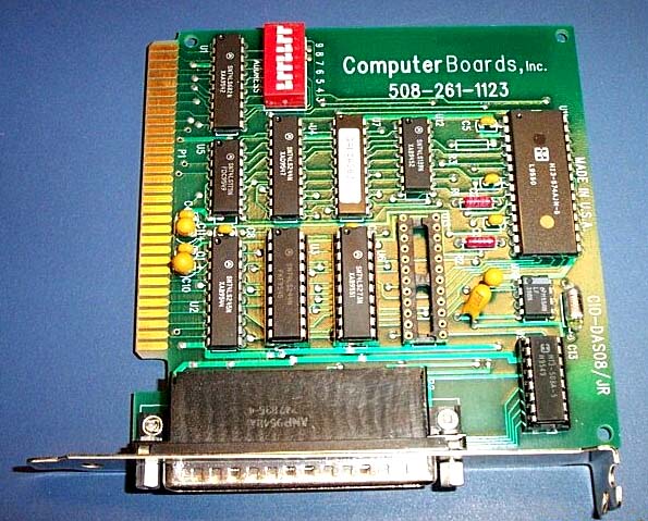
Because of the advent of 2 channel acquisition in LTP222A, I wanted to have the LTP Program work with an inexpensive 2 channel AD board (rather than just relying on the single channel Pico ADC-42 board). After trying several boards, I settled on Measurement Computing's CIO-DAS08/JR-A0 (Fig. 2.3.4.1). It fits into an ISA slot like the Labmaster and Digidata 1200.
NOTE: In general, I think that the DAS08/JR board is very good for 1 AD channel recording (AD channel crosstalk is not an issue), and is better than the Pico board for this because it is easier to install than the Pico board (sorting out the parallel ports can be a problem), and it has two analog outputs (versus none on the Pico board). However, the board is only acceptable for 2 AD channel recording, because there is measurable 1-4 bit AD channel crosstalk, although I think this crosstalk is low enough to live with (particularly when considering the low cost of the board). However, if you are doing 2 AD channel recording, it is best to use a Digidata 1200 board because there is only up to 1 bit AD channel crosstalk.
The DAS08/JR-AO is a simple board that essentially contains an Analog Devices AD574A acquisition chip, sample-and-hold and multiplexer chips, an Analog Devices AD7237 analog output chip, and a TTL output port chip (74LS273N). The only difference between the DAS08/JR-A0 and the DAS08/JR is that the DAS08/JR does not contain any analog output chip and relies on the TTL output port chip for all output. The DAS08/JR-A0 costs ca. £180/$200 and the DAS08/JR costs ca. £140/$150.
|
|
| Fig. 2.3.4.1. Measurement Computing's CIO-DAS08/JR board. Note the empty socket. If an Analog Devices AD7237 analog output chip was inserted into the socket, the board would become a CIO-DAS08/JR-AO (with Analog Output). |
2.3.4.1 Program startup for the DAS08/JR-AO and DAS08/JR boards
| Because the LTP24 program cannot automatically detect if a DAS08/JR-A0 or DAS08/JR board is installed (as it can do for a Digidata 1200 board), an additional word 'das08' must be added to the command line when LTP24 is started in order to use the DAS08/JR-A0 or DAS08/JR board. In addition, there are no set factory settings for the DAS08/JR-A0 or DAS08/JR board base address, so just pick one address (say 340 hexadecimal) and also enter this address on the command line: |
| C:\YOURDATA\010704\> ltp24 das08 340 |
Startup for the DAS08/JR-AO and the DAS08/JR is the same.
2.3.4.2 Measurable AD Channel Crosstalk in the DAS08/JR boards
The 'weakest link' of the DAS08/JR board is a small, but measurable, amount of crosstalk between the 2 AD channels. Note, however, that AD channel crosstalk is NOT a problem when using just 1 AD channel.
If -5 to +5 volts is input into one AD channel, then a 1-4 bit positive shift (usually 1-3 bits) occurs in the other AD channel (see Fig. 2.9.3) Because the 12 bit AD converter in the DAS08/JR has 4096 different levels or 'bits' over the -5 to +5 volt range, the AD channel crosstalk is ~ 4/4000 or ~ 0.1%. However, the crosstalk shift in one AD channel is usually much larger for negative going than positive going input voltages into the other AD channel, so the over the negative input voltage range, the AD channel crosstalk is closer to ~ 0.2%. Furthermore, the amount of crosstalk is roughly proportional to the negative input voltage into one AD channel, such that -2.5 volts input into one AD channel causes only a half the bit shift in the other AD channel.
The AD crosstalk is up to 1 bit in the Digidata 1200 board, and 2-3 bits in the Labmaster board.
However, DAS08/JR boards can be slightly different, so be sure to measure the amount of crosstalk between the two AD channels for your DAS08/JR board (see Section 2.9.3 and also APPENDIX B11).
If you are amplifying well above the 'bit' level, this should not be a problem. In other words, if the EPSP or other signal you are measuring is say 400 levels or bits in amplitude (approximately 1/10th of the full scale of 4096 bits), then a 4 bit shift (caused by the other AD channel going from -5 to +5 volts) would cause a 4/400 or 1% error in amplitude measurement. For example, when measuring extracellular EPSPs, if your AD0 Gain is x1000 and you are recording 4096 different levels over the -5 to +5 volt input range, this means you effectively have ~ 4000 levels or bits in a 10 mV range. Therefore, a signal of 400 levels or bits would be 1/10th of 10mV, or 1 mV. Therefore, for 1% or less error of the EPSP peak measurement, the EPSP amplitude should be at least 1 mV.
While the presence of this AD channel crosstalk is not ideal, I think this is a limitation that can be lived with, especially when considering the low cost of the board. However, if you think this amount of crosstalk is too large, either increase the gain of the AD channel you are measuring from, or use a different board such as the Digidata 1200.
For safety, make sure channels AD2, AD3, AD4, AD5, AD6 and AD7 are grounded (see Fig. 2.3.4.3.2 and Fig 2.3.4.3.3).
Feel free to contact support@winltp.com if you do not understand this and want to use 2 AD channels on this board.
2.3.4.3 Connections for the DAS08/JR-AO and DAS08/JR boards
| For an LTP experiment with one or two recording electrodes (extracellular or intracellular), intracellular (IC) stimulation through the recording electrode (if applicable) and two extracellular stimulating electrodes (S0 and S1), connect the recording electrode amplifier and SIUs to the DAS08/JR-AO or DAS08/JR board using the Electrode Connections Help Box (Fig. 2.3.4.3.1). This information can be viewed in the LTP program by using the menu command: |
| Help -> Electrode<->AD board Connections |
 |
| Fig. 2.3.4.3.1 DAS08/JR-AO and DAS08/JR Electrode Connections Help Box. For the DAS08/JR-AO (having the analog output chip), use DA0 (Analog Out 0) or DigOut5 for S0 stimulation. On the DAS08/JR (with no analog output chip), use only DigOut5 for S0 stimulation. For the DAS08/JR-AO, use DA1 (Analog Out 1) or DigOut4 for IC stimulation, but on the DAS08/JR use only DigOut4 for IC stimulation. |
| To hook up the DAS08/JR-AO (with the analog output chip) use the connections to the DB-37 input/output socket shown in Fig. 2.3.4.3.2. Be sure to ground channels AD2, AD3, AD4, AD5, AD6 and AD7. |
| Fig. 2.3.4.3.2. Connections for the DAS08/JR-AO (with the analog output chip) to the DB-37 socket. Note that Pins 36 or 37 can be used for Digital Ground to connect to coaxial shielding for S1, DO0, DO1 and DO2 digital outputs (and the return path for connecting to the S1 SIU). Also note that Pins 20, 21, 22 or 23 can be used for Analog Ground to connect to coaxial shielding for AD0, AD1, DA0 and DA1 (as well as the return path for connecting to the S0 SIU). |
| To hook up the DAS08/JR (without the analog output chip) use the connections to the DB-37 input/output connector shown in Fig. 2.3.4.3.3. Be sure to ground channels AD2, AD3, AD4, AD5, AD6 and AD7. |
| Fig. 2.3.4.3.3. Connections for the DAS08/JR (without the analog output chip) to the DB-37 socket. Note that Pins 36 or 37 can be used for Digital Ground to connect to coaxial shielding for S0, S1, IC, DO0, DO1 and DO2 digital outputs (and the return path for connecting to the S0 and S1 SIUs). Also note that Pins 20, 21, 22 or 23 can be used for Analog Ground to connect to coaxial shielding for AD0 and AD1. |
To test the board, the simplest way is to buy a 37 pin shielded cable with female DB-37 connectors (C37FFS-5) and a screw terminal board (CIO-MINI37) from Measurement Computing.
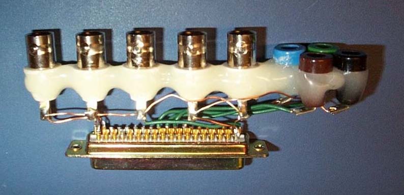
This simplest way of making the connector to the DAS08/JR-AO or DAS08/JR board is to directly solder coaxial cables to the DB-37 socket and put BNC connectors at the other end of the cables (Fig. 2.3.4.4). An important step is then to secure the wires by gluing them in with Epoxy (Araldite).
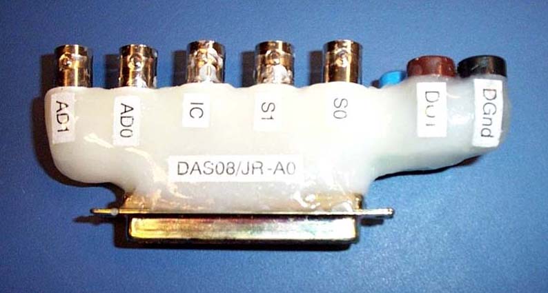
Alternatively, a more complicated connector can be made by soldering BNC and banana sockets directly to the female DB-37 socket. Fig 2.3.4.3.4A shows the epoxyed BNC and banana sockets soldered into the DB-37 connector but not glued in with epoxy. Fig. 2.3.4.3.4B shows a final connector glued in with epoxy. |
|
|
| Fig 2.3.4.3.4A The epoxyed BNC and banana sockets soldered into the DB-37 connector but not glued in with epoxy. |
|
|
| Fig. 2.3.4.3.4B. The final connector glued in with epoxy. |
Also note that the input voltage range on the DAS08/JR-AO and DAS08/JR boards (as with the Pico board) is -5 to +5 volts (in contrast to the -10 to +10 volts on the Labmaster and Digidata 1200 board). For timing errors in Analog input and Digital output sample-to-sample jitter (on the order of 2-5 usec) and sweep-to-sweep jitter with the DAS08/JR-AO and DAS08/JR boards, see the values for the very similar Pico ADC-42 board in APPENDIX B.4 and APPENDIX B.6, respectively.
Finally, note that the fastest the DAS08/JR-AO and DAS08/JR boards can do repeat ADsweep (LTD) stimulation is 1.0 Hz (see APPENDIX B.5).
| Measurement Computing can be located on the Internet at: |
| www.measurementcomputing.com |
|
The DAS08/JR-AO and DAS08/JR boards can also be purchased in the UK from Adapt Scientific at: |
| www.adeptscience.co.uk |
2.3.4.4 Software Calibration of analog inputs and analog outputs
According to the Computing Measurement and Analog Devices specifications on the AD574A chip, the accuracy of the DAS08/JR-AO and DAS08/JR board is a maximum +5 LSBs offset and maximum 0.25% gain error at full scale (which includes the offset error). This inaccuracy is because there are no additional on-board potentiometer offset and gain adjustments. However I have installed software offset and gain calibration that is applied to the sweep data just after the sweep is obtained. For the acquired data, this adjustment is made at the 16 bit level even though the board has only 12 bits accuracy, so this ensures monotonicity.
According to the Computing Measurement and Analog Devices specifications on the AD7237 chip, the accuracy of the DAS08/JR-AO board is about +5 LSBs offset and +5 LSBs gain at full scale (which includes the offset error). This indicates that the DAS08/JR-AO has an accuracy of +5 LSBs at full scale, and +5/2047 or ~ +0.25% inaccuracy at full scale. This inaccuracy is because there are no additional on-board potentiometer offset and gain adjustments. However I have installed software offset and gain calibration that is applied to the stimulation data before the sweep is run. For the output this adjustment is made at the 12 bit level. If the gain is adjusted, this would not produce monotonicity for a triangular wave output (which LTP24 doesn't do anyways), but it means that square pulse amplitudes are slightly more accurate.
|
Considerations about using Software Calibration of the input signal |
|
If you are performing extracellular experiments: |
| a) | A slight offset error should not make any difference, so don't bother adjusting the offset. | ||
| b) | The 0.25% gain error at full scale is probably not important. But if it is, you can adjust it using an accurate and calibrated multimeter of at least 4 and 1/2 digits precision. |
|
If you are performing intracellular voltage or patch clamp experiments: |
| a) |
An offset error may be important, particularly for signals near 0 volts, and the offset can easily be adjusted. |
||
| b) | The 0.25% gain error at full scale may or may not be important. If it is, you can adjust it using an accurate and calibrated multimeter of at least 4 and 1/2 digits precision. The AD board is more accurate than the more common 3 and 1/2 digit multimeters, so using one of these is pointless. |
|
Considerations about using Software Calibration of the analog output signal for the DAS08/JR-AO |
| a) |
An offset error may be important, particularly for signals near 0 volts, and can easily be adjusted. |
|
| b) | The +0.25% gain error at full scale may or may not be important. If it is, you can adjust it using an accurate and calibrated multimeter of at least 4 and 1/2 digits precision. The AD board is more accurate that the more common 3 and 1/2 digit multimeters, so using one of these is pointless. |
WARNING: This software calibration is specific to each DAS08 board. If a new DAS08 board is installed it must be calibrated anew.
Enabling the software calibration
When the LTP24 program starts up, the DAS08/JR-AO and DAS08/JR offset and gain adjustment fields cannot be altered (for protection against inadvertent changing). However, in the Options menu that appears when a DAS08 board is being used, picking Enable DAS08JR offset/gain adjust (Fig. 2.3.4.4.1) enables offset and gain adjustment fields for the DAS08 boards to appear in the Miscellaneous page (Fig. 2.3.4.4.2). Thus the AD0 Offset Adjust field, the AD0 Gain Adjust field, the AD1 Offset Adjust field and the AD1 Gain Adjust field can now be changed. In addition, the DA0/S0 Offset Adjust field, DA0/S0 Gain Adjust field, the DA1/IC Offset Adjust field DA1/IC Gain Adjust field can also be modified.
(Note that the DA1/IC Offset Adjust, and the DA1/IC Gain Adjust fields are actually mistakenly labeled DA1/S1 Offset Adjust, and the DA1/S1 Gain Adjust fields, a cosmetic error that I didn't correct because the 2.30D version was well into beta test by the time I wrote this.)
|
|
| Fig. 2.3.4.4.1. The Options menu that appears when a DAS08/JR-A0 or DAS08/JR board is being used that enables offset and gain adjustment fields to appear in the Miscellaneous page. |
|
|
| Fig. 2.3.4.4.2. Miscellaneous page when the DAS08/JR-AO or DAS08/JR board is running. The AD0 Offset Adjust, AD0 Gain Adjust, AD1 Offset Adjust, AD1 Gain Adjust, DA0/S0 Offset Adjust, DA0/S0 Gain Adjust, DA1/IC Offset Adjust, and the DA1/IC Gain Adjust fields can be modified. (Note that the DA1/IC Offset Adjust, and the DA1/IC Gain Adjust fields are actually mistakenly labeled DA1/S1 Offset Adjust, and the DA1/S1 Gain Adjust fields, a cosmetic error that I didn't correct because the 2.30D version was well into beta test by the time I wrote this.) |
Once the Offset and Gain Adjust fields have been edited they can be 'locked' in place and uneditable by using the Options menu and choosing Disable DAS08JR offset/gain adjust (Fig. 2.3.4.4.3). |
|
|
| Fig. 2.3.4.4.3. The Options menu that appears when a DAS08/JR-A0 or DAS08/JR board is being used that makes the offset and gain adjustment fields in the Miscellaneous page uneditable. |
Software Calibration Proceedure
Note: It is important to perform offset adjustment before gain adjustment.
Analog input adjustment: |
| 1. | First, adjust analog input offset by grounding out the input (connect AD0 and AD1 to AnalogGround, Pins 20, 21,22 or 23) and then use the direct signal measurement at high gain to put in a few bits to the AD0 and AD1 Offset Adjust fields. Because adjustment is at the 16 bit level, I have allowed 1/2 bit offset adjustments to be entered. |
This is very easy to do and requires no special equipment, and for Intracellular or Patch Clamp recording is probably be a good idea. For Extracellular recording it is probably not necessary. |
|
For the DAS08/JR-AO board adjusted in Fig. 2.3.4.4.2, +5 LSBs had to be put into both AD0 and AD1 Offset Adjust fields to have a AnalogGrounded input measure 0 volts. |
|
| 2. | Second, adjust the analog input gain by taking a 1.9 to 4.9 volt DC signal (you can use the DA0 or DA1 outputs when using the DAS08/JR-AO board, or signal generator with the DAS08/JR board) and input it into AD0 or AD1 and into at least a 4 and 1/2 digit accurate and calibrated multimeter, and change the AD0 or AD1 Gain Adjust field until the direct signal measurement at high gain is equal to what the multimeter reads. |
| This is not as easy to do and requires at least a 4 and 1/2 digit multimeter. Do not try this using the more common 3 and 1/2 digit multimeter; it is not accurate enough. | |
For the DAS08/JR-AO board adjusted in Fig. 2.3.4.4.2, both AD0 and AD1 Gain Adjust fields had to be changed to 0.9996 times gain. These boards measured signals 0.04% too large without software compensation. |
Analog output adjustment for the DAS08/JR-AO: |
| 1. | First, for offset adjustment connect the output of DA0 or DA1 to AD0 (and optionally at least a 4 and 1/2 digit multimenter). Then use the direct signal measurement of AD0 at high gain (and/or the multimeter) and put in a few bits to the DA0 or DA1 Offset Adjust fields. Because adjustment is at the 12 bit level, only units of 1 bit offset adjustments can be entered. |
This is very easy to do and requires no special equipment (the 4 and 1/2 digit multimenter is optional). For Intracellular or Patch Clamp analog current or voltage stimulation this offset adjustment would probably be a good idea. |
|
| For the DAS08/JR-AO board adjusted in Fig. 2.3.4.4.2, +1 LSBs had to be put into DA0 and 0 LSBs had to be put into DA1 Offset Adjust fields to have a the analog output measure 0 volts. | |
| 2. | Second, adjust the analog output gain by outputting a 1.9 to 4.9 volt DC signal (you can use a several second long pulse from DA0 or DA1 of the DAS08/JR-AO board) and input it into at least a 4 and 1/2 digit accurate and calibrated multimeter, and change the DA0 or DA1 Gain Adjust field until the direct signal measurement at high gain is equal to what the multimeter reads. |
| This is not as easy to do and requires at least a 4 and 1/2 digit multimeter. Do not try this using the more common 3 and 1/2 digit multimeter; it is not accurate enough. | |
| For the DAS08/JR-AO board adjusted in Fig. 2.3.4.4.2, the DA0 and DA1 Gain Adjust fields had to be changed to 1.0005 and 1.0010 times gain, respectively . These boards output analog signals 0.05% and 0.1% too small without software compensation. |
The
starting of the LTP24 program has drastically changed from the earlier LTP114J
version primarily due to automatic creation of data folders during program
startup. You no longer have to:
1) manually create a data folder, 2) move to that data folder, and 3) start the
LTP program from that data folder, as you had to with LTP114J.
2.4.1
Windows 95/98 Acquisition
Starting Acquisition in the Windows 95/98 MS-DOS Mode
The
LTP program will run on-line in only the MS-DOS Mode of Windows 95 or 98.
LTP24 is started by first going into the MS-DOS Mode and
then starting LTP24 from the DOS command line.
To
put the computer into the MS-DOS Mode
(DOS 7.0), click the 'Start' button, then click the 'Shut
Down' button and click 'Restart the computer in MS-DOS mode'.
Do not click on the MS-DOS icon in Windows 95/98 because this will merely go to
the DOS Compatibility Box. The MS-DOS Mode in Windows 95/98 is not
equivalent to the DOS in the DOS Compatibility Box in Windows 95/98.
Alternatively
during the boot-up process on computers using Windows 95/98, just after the
'Starting Windows 95' or 'Starting Windows 98' line comes up and the computer
beeps, press F8 to go directly into the Windows 95/98 Startup Menu, then
enter 6 for the 'Command prompt only'. This bypasses the need to go into the
Windows 95/98 GUI and then down into the MS-DOS Mode. (After exiting the LTP
program type C:>\ win to enter the Windows 95/98 GUI. If this
seems a bit
like Windows 3.x and "deja vu all over again", it is.)
The
LTP24 (and LTP222A) program can now be started from within ANY folder, in contrast to
LTP114J (and it doesnt have to be the
root folder used here).
|
If using the Digidata 1200 board: |
|
|
C:\> ltp24 |
|
or if using the Digidata 1200 board at a non-default hexadecimal base
address: |
|
|
C:\> ltp24 100 |
|
or if using the Labmaster board: |
|
|
C:\> ltp24 labmaster |
|
or if using the Labmaster board at a non-default hexadecimal base
address: |
|
|
C:\> ltp24 labmaster 100 |
|
or if using a Pico ADC-42 board attached to LPT1 and digital output is
also through LPT1 (or LPT2 or LPT3): |
|
|
C:\> ltp24 pico42_dio_1 |
|
|
C:\> ltp24 pico42_dio_2 |
|
|
C:\> ltp24 pico42_dio_3 |
|
or if using a Pico ADC-42 board attached to LPT1 and digital output is
through LPT2 (or LPT2 and LPT3): |
|
|
C:\> ltp24 pico42_1__dio_2 |
|
|
C:\> ltp24 pico42_2__dio_3 |
When
the LTP program starts up, it automatically determines if the computer is too
slow for the chosen data acquisition board, in which case it terminates.
However, after this initial 'speedtest' the LTP program does not again check if
the computer is fast enough for the data acquisition board. This means that if
there was a microprocessor slowdown (which could occur if the microprocessor
when into a power saving mode on a laptop computer, or if the 'Turbo'
speed was inadvertently turned off), a 100 msec sweep would actually take twice
as long (200 msec) in real time. This would mean that a 10 msec duration EPSP
would actually appear having a 5 msec duration on the ADsweep graph, and the
slope would appear twice as large. If the synaptic potential duration or
slope immediately and inexplicably changes by a factor of two, check that the
synaptic potential duration is right by independently measuring it with an
oscilloscope. Alternatively, if an oscilloscope is not available, restart the
LTP program to test the data acquisition board speed again.
All
single AD waveform files (*.P0, *. BP0, *.FP0, *.AP0, *.LP0 and *.IP0 etc), all Amplitude/Calculation files (*.AMP), and all
LaserJet print files (*.LJ) will be stored in this C:\YOURDATA\010704 start-up
folder. All initialization (*.INI) and protocol (*.PRO) files will be stored in
the program folder C:\LTP24.
2.4.2
Windows 95/98 Reanalysis
You
can start LTP24 program reanalysis by:
1)
Go to the Windows Explorer and click on the ltp24.exe file to run the program
in an DOS box.
2)
Click the MS-DOS prompt to go to the DOS box command line, and from any folder
type in:
C:\>
ltp24
3) Click the supplied desktop reanalysis icon shown below.

Due
to a fault in the Windows 95/98 DOS extender, the LTP program doesnt know how
much RAM memory is available, only if it is too little in which case the program
exits. Therefore, in reanalysis
mode in the DOS box of Window 95/98, the number of samples/sweep has been
limited to 50,000. If you need more
samples/sweep during reanalysis, run the LTP program in the MS-DOS mode, and
use:
C:\LTP24
reanalysis_msdosmode
if
your computer has a Digidata 1200 board installed (which would otherwise be automatically detected
and will send the LTP program into acquisition mode).
2.4.3
MS-DOS 6.x / Windows 3.xx
Acquisition
The
LTP program will acquire data only when started in the 'Real' Command Line
DOS mode. To enter this
mode, just start the computer and don't go into Windows (e.g. do not type C:>win).
If you are already in Windows 3.x, exit Windows completely (File->Exit)
and return back to 'Real' Command Line DOS.
Don't click on the MS-DOS icon in Windows 3.x because this will merely go
to the DOS Compatibility Box. 'Real' Command Line DOS is not
equivalent to the DOS in the DOS Compatibility Box in Windows.
The
LTP24 program can
now be started from within ANY folder, in contrast to LTP114J (and it doesnt have to be the
root folder used here).
|
If using the Digidata 1200 board: |
|
|
C:\> ltp24 |
|
or if using the Digidata 1200 board at a non-default hexadecimal base
address: |
|
|
C:\> ltp24 100 |
|
or if using the Labmaster board: |
|
|
C:\> ltp24 labmaster |
|
or if using the Labmaster board at a non-default hexadecimal base
address: |
|
|
C:\> ltp24 labmaster 100 |
|
or if using a Pico ADC-42 board attached to LPT1 and digital output is
also through LPT1 (or LPT2 or LPT3): |
|
|
C:\> ltp24 pico42_dio_1 |
|
|
C:\> ltp24 pico42_dio_2 |
|
|
C:\> ltp24 pico42_dio_3 |
|
or if using a Pico ADC-42 board attached to LPT1 and digital output is
through LPT2 (or LPT2 and LPT3): |
|
|
|
|
C:\> ltp24 pico42_1__dio_2 |
|
|
|
|
C:\> ltp24 pico42_2__dio_3 |
When
the LTP program starts up, it automatically determines if the computer is too
slow for the chosen data acquisition board, in which case it terminates.
However, after this initial 'speedtest' the LTP program does not again check if
the computer is fast enough for the data acquisition board. This means that if
there was a microprocessor slowdown (which could occur if the microprocessor
when into a power saving mode on a laptop computer, or if the 'Turbo'
speed was inadvertently turned off), a 100 msec sweep would actually take twice
as long (200 msec) in real time. This would mean that a 10 msec duration EPSP
would actually appear having a 5 msec duration on the ADsweep graph, and the
slope would appear twice as large. If the synaptic potential duration or
slope immediately and inexplicably changes by a factor of two, check that the
synaptic potential duration is right by independently measuring it with an
oscilloscope. Alternatively, if an oscilloscope is not available, restart the
LTP program to test the data acquisition board speed again.
All
single AD waveform files (*.P0, *. BP0, *.FP0, *.AP0, *.LP0 and *.IP0 etc), all Amplitude/Calculation files (*.AMP), and all
LaserJet print files (*.LJ) will be stored in this C:\YOURDATA\010704 start-up
folder. All initialization (*.INI) and protocol (*.PRO) files will be stored in
the program folder C:\LTP24.
2.4.4
MS-DOS 6.x / Windows 3.x
Reanalysis
Just
go to the File Manager and click on the ltp24.exe file to run the program in
an DOS box.
Alternatively,
click the MS-DOS prompt to go to the DOS box command line, and from any folder
type in:
C:\>
ltp24
Due
to a fault in the Windows 3.xx DOS extender, the LTP program doesnt know how
much RAM memory is available, only if it is too little in which case the program
exits. Therefore, in reanalysis
mode in the DOS box of Window 95/98, the number of samples/sweep has been
limited to 20,000. If you need more
samples/sweep during reanalysis, run the LTP program from the command line in
Real DOS and use:
C:\LTP24
reanalysis_msdosmode
if
your computer has a Digidata 1200 board installed (which would otherwise be automatically detected
and will send the LTP program into acquisition mode).
LTP24 can only be used in acquisition mode if the computer is booted up into DOS 6.x or DOS 7.0. Windows ME is similar to Window 95/98 with the exception that it has no MS-DOS (real DOS) mode (which is too bad because that is what LTP24 uses in the acquisition mode).
Remember that using LTP24 for acquisition also requires the Windows ME computer to have an ISA bus (although the Pico ADC-42 board may work without it).
However, a computer
using Windows ME can be booted up into DOS 7.0. The simplest thing
to do is to format a 1.44 MB floppy disk in a Windows 98 computer (C:\format a:
/s from the DOS command line). Put
the floppy disk into the A: drive of the Windows ME computer, and
start the computer. For these
computers, if the computer starts up with a disk in floppy drive A: that has
been formatted with DOS 7.0 (e.g. in a Windows
98 computer), then the operating system used to format that floppy (DOS 7.0 of
Windows 98) will be the operating system that the computer with Windows ME installed actually will run in. In other words, putting
in a floppy disk formatted in a DOS 7.0 (Windows98) computer causes the Windows
ME computer to become a DOS 7.0 (Windows 98) computer.
Alternatively, you can
use a program such as Partition Magic to
You
can start LTP24 program reanalysis by:
1)
Go to the Windows Explorer and click on the ltp24.exe file to run the program
in an DOS box.
2)
Click the MS-DOS prompt to go to the DOS box command line, and from any folder
type in:
C:\>
ltp24
3)
Click the supplied desktop reanalysis icon (for Windows 98) shown below.
Due
to a fault in the Windows ME DOS extender, the LTP program doesnt know how
much RAM memory is available, only if it is too little in which case the program
exits. Therefore, in reanalysis
mode in the DOS box of Window 95/98, the number of samples/sweep has been
limited to 50,000. If you need more
samples/sweep during reanalysis, restart the computer in DOS 7.0 (MS-DOS mode),
run the LTP program in the MS-DOS mode, and
use:
C:\LTP24
reanalysis_msdosmode
if
your computer has a Digidata 1200 board installed (which would otherwise be automatically detected
and will send the LTP program into acquisition mode).
2.4.7
Windows NT, 2000 or XP Acquisition
LTP24 can only be used in acquisition mode if the computer is booted up
into DOS 6.x or 7.0. And because DOS 6.x requires FAT and DOS 7.0 requires
FAT or FAT32 file systems, at least one hard disk partition in the Window NT, 2000
or XP computer requires a FAT or FAT32 file system. If NTFS is
the only file system being used,
convert it to FAT or (better yet) FAT32 using a program such as Partition Magic 6.
Remember that using LTP24 for acquisition also requires the Windows NT/2000/XP computer to have an ISA bus (although the Pico ADC-42 board can work without it). The Pico board, using the parallel port, will work on at least some of the computers having only a PCI bus (including the Dell 8200 1.8GHz Pentium 4 computer with a thin screen monitor).
Then the simplest thing
to do is to format a 1.44 MB floppy disk in a Windows 98 computer (C:\format a:
/s from the DOS command line). Put
the floppy disk into the A: drive of the Windows NT, 2000 or XP computer, and
start the computer. For these
computers, if the computer starts up with a disk in floppy drive A: that has
been formatted with DOS 7.0 (e.g. in a Windows
98 computer), then the operating system used to format that floppy (DOS 7.0 of
Windows 98) will be the operating system that the computer with Windows NT, 2000
or XP installed actually will run in.
Alternatively, you can
use a program such as Partition Magic to
2.4.8
Windows NT, 2000 or XP Reanalysis
You
can start LTP24 program reanalysis by:
1)
Go to the Windows Explorer and click on the ltp24.exe file to run the program
in an DOS box.
2)
Click the MS-DOS prompt to go to the DOS box command line, and from any folder
type in:
C:\>
ltp24
3)
Click the supplied desktop reanalysis icon shown below.

Due
to a fault in the Windows 2000 DOS extender, the LTP program doesnt know how
much RAM memory is available, only if it is too little in which case the program
exits. Therefore, in reanalysis
mode in the DOS box of Window 95/98, the number of samples/sweep has been
limited to 50,000. If you need more
samples/sweep during reanalysis, restart the computer in DOS 7.0 (MS-DOS mode),
run the LTP program in the MS-DOS mode, and
use:
C:\LTP24
reanalysis_msdosmode
if
your computer has a Digidata 1200 board installed (which would otherwise be automatically detected
and will send the LTP program into acquisition mode).
2.5
Automatic data
folder creation at startup, AutoCreate a new data
folder, and Change data folder
2.5.1
Automatic Data Folder creation at startup
When LTP24 starts up,
the first screen shown below is a splash screen (Fig. 2.5.1, top panel) that
shows whether the program is in Reanalysis Mode or in Acquisition Mode (by
showing which data acquisition board is in use and at which I/0 port location or
LPT port number). Fig. 2.5.1 shows that
here the LTP program is running in acquisition mode and that it is using the
Labmaster board at I/O location hexidecimal 710. A dialog box (Set Data Folders) is presented in the
splash screen which allows you to either Create a New Data Folder,
which you would do if you were to Run an Experiment and to put your data for the
day into a new data folder.
Alternatively, you could choose to Use an Existing Data Folder if
you were reanalysing data.
If you decided to
Run an Experiment the Running Experiment
dialog box would be
presented (next dialog box down) which requests that you to fill in
a data root drive and folder. The
data root folder is the folder off of which all subsequent data folders
will be created. In Fig. 2.5.1, the
data drive folder is C: and the data root folder is the folder containing the
LTP program, \LTP22XX (just think of the LTP program being LTP22XX instead of
LTP24
for the purposes of Fig. 2.5.1). The
LTP program folder C:\LTP22XX (e.g. C:\LTP24) is the default data root folder
that is presented upon initial startup. Therefore
if today was July 4, 2001, then the data folder into which the *.P0, *.AMP and
*.LJ files would be written would be C:\LTP22XX\010704, and this data folder
would be automatically created. The first two characters of the data folder denote decade and
year, the second two characters denote month and the third two characters denote
day of the month. With this method,
folders are automatically sorted year/month/day when viewed with the Windows
Explorer.
Alternatively, if you
have two people using one computer to run experiments, the data root drive and
folder could be changed to a non-default data root folder such as C:\BILLDATA,
and the data folder automatically created on July 4, 2001 would be C:\BILLDATA\010704.
The other person would just have to change the data root folder on LTP
program startup to their data root folder.
Alternatively, if you are reanalysing data, choose the Use Existing Data Folder option in the Set Data Folders dialog box and the Reanalyzing Data dialog box appears (see Section 6.1).
|
|
| Fig. 2.5.1 Automatic Data Folder creation at program startup to Run Experiment |
2.5.2
AutoCreate a new Data Folder (using CTL-F) while running an
experiment
While running an experiment that saves several thousand ADsweep files, we have found that the speed at which files are saved decreases when over a thousand files are saved to a folder. To fix this problem I added the ability to AutoCreate a new data folder while running an experiment. This can be accomplished by choosing AutoCreate new data Folder in the File menu (Fig. 2.5.2.1). Alternatively, you can quickly AutoCreate a new data folder on-the-fly (e.g. while saving ADsweeps) just by pressing the CTL-F hotkey.
|
|
| Fig. 2.5.2.1.
The File menu showing the AutoCreate new data Folder
CTL-F selection. |
When this is done, the data folder is changed from C:\ltp22XX\010704 to the newly created data folder C:\ltp22XX\010704B (Fig. 2.5.2.2). Up to 26 data folders (e.g. up to C:\ltp22XX\010704Z) can be AutoCreated in this manner.
|
|
| Fig. 2.5.2.2. After
AutoCreating new data Folder using CTL-F. |
When saving ADsweeps to
a hard disk having a FAT32 file system, the AutoCreate a new data folder is
unmeasurably fast, but when saving to a hard disk having the older FAT (16) file
system, the AutoCreation can take several seconds.
It is therefore better to use a FAT32 file system if speed is needed.
2.5.3 Change to a different data folder during acquisition
If you wish to change
to a different data folder during either acquisition or reanalysis you can
choose the Change data folder
selection in the File menu (Fig. 2.5.2.1) to
bring up the dialog box in Fig. 2.5.3.1.
 |
|
Fig. 2.5.3.1. Change Folder Dialog Box. |
Choosing Using Same Read/Write Data Folder allows you to set the Read/Write data drive and data folder by presenting the Using Same Read/Write Data Folder dialog box in Fig 2.5.3.2. Changing this dialog box can set the Read/Write data folder say back to the original C:\LTP22XX\010704 data folder.
|
|
| Fig. 2.5.3.2. Using Same Read/Write Data Folder dialog box |
2.6 Set the AD Gain, DataType, Sample Interval and Other Parameters
2.6.1 Set the AD Gain, Data Type, and Sample Interval in the Miscellaneous Window
| The Data Type Unit determines whether the LTP program is in extracellular or intracellular current clamp mode, or in patch clamp voltage clamp mode. To set the AD channel mode, go to the Miscellaneous Window (shown in Fig. 3.1.6) using PgDn until the last window is reached, or a use the menu commands (see Fig. 3.4.6A,B) |
| Window -> Miscellaneous values |
| and type in the Data Type Unit: |
|
First, set the channel AD0 DataType to "mV".
Second, change the AD0 gain to be equal to the total amplification gain from the electrode to the AD board connection. For example, if an Axon Instruments AxoClamp is used in current clamp mode with an internal x10 output gain, which then goes into an external x100 amplifier and then into channel AD0, the AD0 Gain would be 1000.
Alternatively iif an Axon Instruments AxoPatch 1D or 200B is used in whole cell voltage clamp mode (with a CV-04 1/100 headstage where beta = 1), with an output gain of alpha = 10, and with the output going channel AD0, the channel AD0 Gain would be the following:
|
(Yes that's 10 0's!) If the output gain is changed to = 20, the AD0 Gain increases to 20000000000. Then set the channel AD0 DataType to "pA".
In LTP24 I have added the capability to change the gain by alternatively entering it in AD0 Units/V (Fig. 2.6). While maybe it is clearer to just type an AD Gain of 1000 for an extracellular or intracellular experiment in "mV", with a patch clamp experiment in "pA" with enormous gain, a AD Units/V of 100 pA/V is much clearer than an AD Gain of 10000000000.
|
|
| Fig. 2.6. Setting the AD DataType Units in mV or pA, and the gain as either the AD Gain or in AD Units/V. |
Third, set the PulseSweep ADinterval to 100 usec.
2.6.2 Set the Digital-to-Analog Output
There is no conversion or gain controlling the DA output voltage. The PulseVolt value you enter (in volts; see Fig. 3.1.2) is the output voltage you get (in volts) from the Labmaster or Digidata 1200 Digital-to-Analog output channel.
| For example, if you are using an Axon Instruments' Axopatch 200B, there is a 50:1 attenuation from the voltage input into the Axopatch 200B, and the output voltage to your voltage-clamped pipette. Therefore you need to set the Rm PulseVolt to: |
| PulseVolt 0.050v (not PulseVolt 0.001v!) |
| in the LTP program to output 50mV (not 1mV!) from the Labmaster or Digidata 1200 DA, and input that 50mV voltage into the Axopatch 200B to produce a |
| 1 mV voltage-clamp command pulse. |
2.6.3 Set the PulseSweep P0 Stimulation Values in the PulseSweep P0 Stimulation Window
| Go to the PulseSweep P0 Stimulation Window (shown in Fig. 3.1.2) by pressing PgDn or PgUp until the correct window is reached. Alternatively use the menu commands (see Fig. 3.4.6A,B) |
| Window -> Pulse P0 stimulation |
Set Pulse stimulation values (see Section 4.5).
2.7 Analog Filtering of the Signal Before Digitization
The waveform signal data should be filtered before being digitized with an analog filter set to half or less of the digitization frequency. For example, if you are acquiring an AD sample at 100 usec intervals (e.g. at 10 KHz sampling frequency), the analog filter should be set to at maximum 5 kHz (1/2 the sampling frequency), or preferably to 2 kHz or lower (except if doing an Rs exponential fit, then keep it at 5 KHz). If the analog filter is set to higher than half the sampling frequency (for example to 10 kHz in the above example), mysterious things can begin to happen due to anti-aliasing such as loosing the capacitative transients (e.g. the Rs measurement) that occur during the voltage clamp pulse when patch clamping.
The analog filter can either be part of the biological amplifier such as the one on the AxoPatch 1D patch-clamp amplifier, or it can be a separate analog filter between the amplifier and the data acquisition board input. Generally, the best analog filters for electrophysiology are Bessel filters because they cause no overshoots, only phase lags.
2.8 Pressing a Function Key to Stimulate and Acquire Data
| In the LTP program, protocols are initiated either by pressing a Function Key or by using the menu commands (see Fig. 3.4.5A,B,C), for example: |
| Run -> "Pulse stimulation (P0) F5" |
| or just press Function Key (for example): |
| F5 |
For the simplest situation of outputting one stimulus pulse (which can be measured with an oscilloscope) and simultaneously acquiring one sweep of data (an ADsweep), press function key F5.
Examine Train output on an oscilloscope or a chart recorder by pressing CTL-F8.
2.9 Check that the Data Acquisition and Stimulation are Working Correctly
The Data Acquisition / Stimulation functions should be carefully examined by:
2.9.1 Input a triangular waveform
Input a known (calibrated) signal using voltage and time calibrated stimulator and see if the correct values are plotted on the AD sweep graphs. Be sure to measure waveform acquisition timing by using a TRIANGULAR WAVEFORM input to make sure no delays occur during the data acquisition/ stimulation sweep. If there is a timing delay, the ramp will not be smooth, but will appear to instantaneously jump to a higher voltage and then continue (Fig. 2.9.1). Ramps can also be used to test if the slope calculation is working correctly (see Section 4.7.3)
|
|
| Fig. 2.9.1. What a triangular waveform would look like if a ca. 2 msec interruption occurred in the computer during the sweep (Calibration: 2V, 6ms). This bug has actually been found on some newer Dell computers (see Rare but serious bug in LTP24). |
2.9.2. Measure Sample-to-Sample Jitter with an Oscilloscope
Use a calibrated oscilloscope to measure the voltage and timing of Analog or Digital output pulses that are generated during Pulse and TrainSweeps. This will test for sample-to-sample jitter because both Analog input and Analog/Digital output occur at about the same time because an AD conversion always starts when an Analog/Digital output occurs. For example, the sample-to-sample jitter can be tested by measuring the width of an S0 pulse during a train (Fig. 2.9.2).
|
|
| Fig. 2.9.2. 4 usec jitter (+/- 2 usec) on a train of 100 usec S0 Pulses. |
2.9.3. Check AD Channel Crosstalk in the Measurement Computing's CIO-DAS08/JR-AO and Labmaster boards
The 'weakest link' of the DAS08/JR board is a small, but measurable, amount of crosstalk between 2 AD channels (see Section 2.3.4.2 and also APPENDIX B11). Note, however, that AD channel crosstalk is NOT a problem with the DAS08/JR board when using just 1 AD channel.
If -5 to +5 volts is input into one AD channel, then a 1-4 bit positive shift (usually 1-3 bits) occurs in the other AD channel. In contrast, the Digidata 1200 has only up to 1 bit shift.
Just remember that if you are amplifying well above the 'bit' level, this should not be a problem. In other words, if the signal you are measuring is say 400 bits in amplitude (approximately 1/10th of the full scale of 4096 bits), then a 4 bit shift (caused by the other AD channel going from -5 to +5 volts) would be a 1% error.
Futhermore, the Labmaster board also has a small, but measurable, amount of crosstalk between 2 AD channels (see Section 2.3.2.2 and alsoAPPENDIX B11). AD channel crosstalk is NOT a problem with the Labmaster board when using just 1 AD channel. If -10 to +10 volts is input into one AD channel, then a 2-3 bit shift occurs in the other AD channel.
There are two basic ways to measure the AD channel crosstalk, directly testing the DAS08/JR or Labmaster board in the computer, and testing the DAS08/JR or Labmaster board at your setup before an experiment.
To directly testing the DAS08/JR or Labmaster board in the computer, connect the IC analog output to one AD channel (e.g. AD0) and ground the other AD channel (e.g. AD1). Put a -5 to +5 (or -10 to +10) volt signal of substantial duration (say 50 msec per pulse) out of IC. Change the AD0/AD1 DataTypes to "V", change the AD0/AD1 Gains to x1, and put the AD0 sensitivity to a low value (ca 10V (or 20V) peak-to-peak), and the AD sensitivity to a very high value (ca. 0.02V peak-to-peak). Then measure the shift in the grounded AD channel, AD1 (Fig. 2.9.3). Use AvgAmp (and therefore also Baseline) to record the shift in voltage by setting the Baseline cursors during the other AD0 channel's -5 (or -10) volt pulse, and the AvgAmp cursors during AD0 channel's +5 (or +10) volt pulse. Because analysis and reanalysis is done at the 16 bit level with the DAS08/JR boards, the values will be to within 1/16th bit. Analysis and reanalysis is still done at 12 bits on the Labmaster board. Also try different IC output voltage regemes.
Then repeat the procedure by connecting the IC analog output to AD1, and ground AD0.
Alternatively, particularly if you are using the DAS08/JR board (without the analog outputs), use the -5 to + 5 volt square wave input from an external waveform generator to test AD channel crosstalk.
The shift in AD1 voltage for the DAS08/JR board should be up to 4 bits positive when AD0 goes from -5 to +5 volts. The shift in AD0 voltage should be up to 4 bits positive when AD1 goes from -5 to +5 volts. The shift in AD1 voltage for the Labmaster board should be up to 3 bits when AD0 goes from -10 to +10 volts. The shift in AD0 voltage should be up to 3 bits when AD1 goes from -10 to +10 volts. Any substantial increase in these values indicates a problem, and it is questionable whether this DAS08/JR or Labmaster board should be used for 2 AD channel recordings. Choose a Digidata 1200 board instead.
In the measurements taken in Fig. 2.9.3 for the DAS08/JR board, going from -5 to +5 volts in AD0 caused about a 0.8 bit positive shift in AD1. Note how the -5 volt pulse was much more effective in causing a bit shift than the +5 volt pulse.
To test the DAS08/JR or Labmaster board at your setup before an experiment, say if you are measuring an EPSP in AD1, turn down the amplification to AD1, and put out a fairly long (ca. 50 msec) pulse into AD0 by say using an electrode test measuring pulse or a voltage clamp pulse such that the pulse would go from 0 to -5 (or -10) volts, and 0 to +5 (or +10) volts at the AD0 input. You could even try grounding out the input to AD1. Measure the shift in AD1 by using AvgAmp.
The shift in AD1 voltage for the DAS08/JR should be up to 4 bits positive when AD0 goes from -5 to +5 volts. The shift in AD1 voltage for the Labmaster should be up to 3 bits positive when AD0 goes from -10 to +10 volts. Any substantial increase in these values indicates a problem, and it is questionable whether this DAS08/JR or Labmaster board should be used for 2 AD channel recordings. Choose a Digidata 1200 board instead.
Feel free to contact support@winltp.com if you do not understand this and want to use 2 AD channels on this board.
2.10.1. Hewlett-Packard LaserJet and Compatible Printers
The LTP program runs with Hewlett-Packard LaserJet II compatible printers (II, III, 4, 5 and 6 etc.) using PCL4 graphics commands. Moderately high resolution (300 dots/inch) plots of ADsweep and Amplitude/Slope graphs are output to the LaserJet printer.
| To choose the printer, use the menu commands (see Fig. 3.4.4): |
| Options -> Printer/plotter |
and then from the upper group of the dialog box choose either 'None' or 'HP LaserJet II, III, 4, 5, 6' (Fig. 2.10.1).
If you are using a printer, connect the parallel printer port on the printer to parallel printer port LPT1, LPT2 or LPT3 on the computer, then from the lower group of the dialog box choose either 'LPT1', 'LPT2' or 'LPT3'. If you are already using a Pico board with digital output on LTP1 or LTP2, make sure this does not conflict with printer usage.
These values determining hardware specifications are automatically saved in the hardware.ini initialization file every time a new value is entered.
2.10.2. Hewlett-Packard DeskJet and Compatible Printers
The LTP program does not specifically support the popular Hewlett-Packard DeskJet and similar inkjet printers, but we have found through trial and error that the LTP program can plot ADsweep and Amplitude/Slope graphs to the Hewlett-Packard DeskJet 870cxi, and may well do so for other deskjet/inkjet printers. Just choose 'HP LaserJet II, III, 4, 5, 6' from the upper group of the Printers dialog box (see Fig. 2.10.1). You just have to try your DeskJet/inkjet printer to find out if this will work.
Although plotting the Amplitude/Slope calculation graphs worked fine, we did notice that only one ADsweep graph could be plotted per page (say out of four). This problem has not been corrected.
2.10.3. Other Printers/Plotters
The LTP24 program does not support Epson FX80 compatible printers, Postscript language printers or Hewlett-Packard 7475 compatible plotters, and will not do so in the future.
2.11 Printing an AD Waveform Graph to the Printer
| If the computer is connected to a Hewlett Packard LaserJet II, III, 4, 5, 6, or compatible printer, print an AD waveform to the printer by pressing ALT-S and ALT-P to elicit the following menu commands (Fig. 3.4.2): |
| SweepFile -> Plot graph to printer/plotter |
| Then press Alt-S, Alt-E and Alt-P to eject the printer page if less than four plots have been graphed: |
| SweepFile -> Eject plot page -> Eject printer/plotter page |
If the program has performed the above tasks, it is ready to be set-up in more detail for your particular experiment (Chapter 4).