- View sweeps by clicking on an Analysis
Graph data point - Impose single and averaged sweeps
- Quarantine bad sweeps in reanalysis
- PopSpike Area, Amplitude & Latency
- Three types of Slope measurement
- Analyze all EPSPs in a sweep
- Special analyses of trains Rs measurement from unfiltered trace
- Convert WinLTP data files to ABF files
- Reanalysis of ABF, IBW and WCP files
| Quick Install and Start |
Quick Install
This Quick Install is only specifically for the National Instruments PCIe-6321 (with the BNC-2110 connector box), the USB-6341 (with screw terminal), and USB-6341 BNC boards. These are the current workhorse boards for WinLTP. For other National Instruments boards see Section 2.4 of the WinLTP Manual.
Install WinLTP
First, download the Install_WinLTP230.exe program from the WinLTP website. Then click on the Install program to install WinLTP. It is best if you install WinLTP into the default C:\WinLTP folder - do not install it under the 'Program Files' folder.
If you are upgrading WinLTP, before installation of WinLTP 2.32 you will have to uninstall your old version of WinLTP. Also see the FAQ 3. How do you Copy Over a Protocol File from an Old WinLTP Program to a New Program?
Install the NI-DAQmx driver and the National Instruments Board
Next, install NI-DAQmx from the DVD included with your M- or X-Series board, or download the latest version (19.6 or later) from www.ni.com. Follow the NI-DAQ installation instructions, and choose the 'Typical' installation. NOTE: for Windows 10 you must use NI-DAQmx version 15.5 or later.
Next, turn off the computer and install the PCIe-6321 board in a PCI express slot, or connect the USB-6341 to the USB 2 or 3 port.
Then restart the computer. The Found New Hardware wizard will then run, and you should choose '(*) Install the software automatically (recommended)' and the wizard should say that it has finished installing the software for the 63xx board.
Then click the 'NI MAX' desktop icon to run the Measurement and Automation Explorer, click on 'Devices and Interfaces', click on 'PCIe-6321', 'USB-6341'or 'USB-6341 BNC' and make sure the device number is "Dev1" (if not, right mouse click and Rename it to “Dev1”), then click the 'Self-Test' button and make sure "The self test completed successfully".
To see the stimulation outputs, for the PCIe-6321/BNC-2110 or the USB-6341 BNC boards connect the 'P0.0' digital output pin to the 'User 1' pin, and connect the 'P0.1' pin to the 'User 2' pin. Then to connect the P0.0 output to AnalogIn0 ('AI 0') by connecting a BNC from 'User 1' to 'AI 0'. And to connect the P0.1 output to AnalogIn1 ('AI 1') by connecting a BNC from 'User 2' to 'AI 1'.
For the USB-6341 (with
screw terminals), directly connect the 'P0.0' digital output (pin
65) to AnalogIn0+ (AI 0, pin 1), and connect
the AnalogIn0-
(AI 8, pin 2) to AI GND
(pin3). Then connect
P0.1 (pin 66) to AnalogIn1+ (AI
1, pin 4) , and connect the
AnalogIn1- (AI 9, pin 5) to
AI GND (pin 6).
Quick Start
Start WinLTP
To start the WinLTP program, click on the 'WinLTP M,X-series' icon. You will be told you are entering the 60 day Demotrial Period where you have access to all of WinLTP's capabilities.
Then during the first startup, you will be presented with the 'Connector Box and Recording Mode' dialog. If you are using the PCIe-6321 and the BNC-2110 connector box, choose the 'BNC-2110' connector box, and then choose the 'Differential Recording Mode'. If you are using the USB-6341-BNC, choose the 'USB board with BNC connectors' and the 'Differential Recording Mode'.
Next during the first startup, you will be presented with the 'Calibrate M- or X-Series Board' - just click the 'Calibrate' button. If you have any problems here, disconnect the cable to the connect box at the connector on the data acquisition board, and then try recalibrating.
Run the Protocol
|
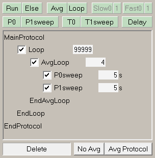
After installing the data acquisition board and starting the WinLTP program, WinLTP will be running the default protocol of alternating S0/S1 pulse stimulation with signal averaging (right).
|
 |
| To start recording, |
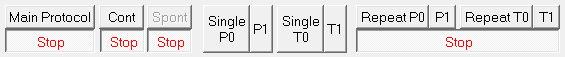
| 1. | click the 'Main Protocol' button (below), then | |
| 2. | click the 'Single T0' button click to evoke a S0 pulse Single Train, then | |
| 3. | click the 'T1 button to evoke S1 pulse Theta Burst stimulation, then | |
| 4. | click the 'Repeat P0' button to evoke S0 Low Frequency Stimulation that induces Long Term Depression, and | |
| 5. | to stop, click the 'Stop' button under the 'Main Protocol' button |
 |
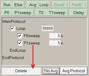 |
To have alternating S0/S1 stimulation without signal averaging, click the 'No Avg' button (left). To have only repetitive S0 stimulation, drag the P1sweep down to the 'Delete' panel (arrow). To restore alternating S0/S1 stimulation with signal averaging, click the 'Avg Protocol' button. |
|
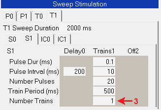
Finally, to change from the S1 pulse Theta Burst stimulation to a Single Train stimulation, all you have to do is decrease the Number of Trains from 3 to 1 |
 |
For more complicated protocols, add P0 and P1sweeps (usually used for single or dual pulse stimulations), T0 and T1sweeps (usually used for train induction stimulations), Delays, non-averaging Loops ('Loop'), Averaging Loops ('Avg') and other functions by clicking on the green buttons above and draging them down into the Protocol Builder script.
To patch clamp, load the 'PatchClampLTP.pro' file using the File -> Open menu.
Look over the winltp.com website and the WinLTP manual to understand the program's full capabilities.