Chapter 4 - RUNNING THE LTP PROGRAM
In the Getting Started section an initial configuration of the program has been performed. This includes:
4.1 Automatic and Manual Loading of the Protocol (*.pro) File from Disk
If you have already developed custom protocols to run your particular experiment, the last protocol file used will be the one automatically loaded when the program is later restarted. However, if there was never any protocol file saved, then only the integral default values will used.
Alternatively, if you wish to load a different protocol file, use the menu command (Fig. 3.4.1A):
File -> Open
to load the Protocol File Dialog Box (Fig. 3.4.1B), then:
| Press TAB to go to the files to choose from. | ||||
| Then press Enter to load the protocol file chosen. |
or:
type the filename (with a "pro" extension) in the filename line.
4.2 Choosing the Basic Protocol
If a custom Protocol File to run your particular experiment has not yet been developed, the following procedures should be performed to fully implement the protocol. Essentially this involve:
To choose a Basic Protocol use the menu commands (Fig. 3.4.1A):
File -> Basic Protocol
The Choose Basic Protocol dialog box is in three sections (Fig. 3.4.1D). The top section shows the following choices:
| Extracellular Electrode Stimulation Protocol |
| ( ) One Sweep Stimulation (P0 only) | ||||||
| ( ) Two Sweep Stimulation (P0 or P1) | ||||||
| ( ) Alternating Two Sweep Stimulation (P0 and P1) |
One Sweep Stimulation (P0 only) causes a repetitive generation of PulseSweep P0 with concurrent data acquisition. Two Sweep Stimulation (P0 or P1) causes a repetitive generation of either PulseSweep P0 or PulseSweep P1 with concurrent data acquisition. Alternating Two Sweep Stimulation (P0 and P1) causes an alternating repetitive generation of both PulseSweep P0 and then PulseSweep P1 with concurrent data acquisition. Note that if either the Two Sweep Stimulation or Alternating Two Sweep Stimulation protocol is chosen, extra Windows are formed for a Train T1 Stimulation Window and a Pulse T1 Stimulation Window and the Windows Menu choices reflect this change (compare Fig. 3.4.7 A versus B and C).
The way we normally run LTP experiments, PulseSweep P0 normally generates S0 only, and PulseSweep P1 normally generates S1 only. Therefore, with the Alternating Two Sweep Stimulation, alternating PulseSweep P0 and PulseSweep P1 generation causes alternating extracellular stimulation, S0 and S1. Also note that in this version of the LTP program (LTP113E), only the first S0 pulse of PulseSweep P0 has synaptic potential calculations performed on it, and only the first S1 pulse of PulseSweep P1 has synaptic potential calculations performed on it. S1 pulses in PulseSweep P0, and S0 pulses of PulseSweep P1 have no synaptic potential calculations performed on it. This limitation will be generalized in a future version of the LTP program.
The bottom section of the Basic Protocol Dialog Box (Fig. 3.4.1D) shows the following choices:
| Digital Filtering or Signal Averaging Protocol |
| ( ) None | ||||||
| ( ) Digital filtering (save raw AD sweeps to disk) | ||||||
| ( ) Signal averaging (save raw and averaged AD sweeps to disk) | ||||||
| ( ) Signal averaging (save averaged AD sweeps to disk) |
If None is chosen, the sweeps are neither digitally filtered or signal averaged. These ‘raw’ ADsweeps are saved to disk.
If Digital Filtering is chosen, each sweep is first acquired and plotted in Grey, and then digitally filtered at an appropriate frequency and plotted in LightBlue. The setting for digital filtering frequency is set by the Filter cutoff frequency field (-3 dB) in the Pulse Detection Window (Figure 4.2.1). However, because of digitally filter boundary problems at the beginning and end of the sweep, only the raw (unfiltered) AD sweeps can be saved to disk.
If Signal Averaging is chosen each sweep is first acquired and plotted in Grey, then the average of the sweeps is then plotted in LightBlue. The setting for the number of sweeps to average is set by the Num Slow Sweeps to Avg field in the Pulse S0 Stimulation Window (see Fig. 4.4.6). Either only the averaged AD sweeps can be saved to disk (with either a *.AP0 (for PulseSweep P0 stimulation) or *.AP1 (for PulseSweep P1 stimulation) file extension), or the average sweeps and the raw sweeps (with an *.P0 (for PulseSweep P0 stimulation) or *.P1 (for PulseSweep P1 stimulation) file extension) can be saved to disk.
Note that this version of LTP113E cannot digitally filter the averaged sweeps on-line. However, averaged sweeps can be digitally filtered during off-line Reanalysis (see Section 5.3). This capability will be added in a future version of the LTP program.
Fig. 4.2.1. Digitally filtering an ADsweep waveform at the Filter cutoff freq of 500Hz (-3dB cutoff frequency) in the Pulse Waveform Detection Window. The raw, unfiltered ADsweep is shown in Grey and the filtered data is shown in LightBlue.
4.3 Setting the Data Acquisition Values
Go to the last ‘Miscellaneous’ window using either PgDn or the menu (Fig. 3.4.7)
Window -> Miscellaneous
and set the appropriate AD sample interval, AD channel gain and AD channel data type in the appropriate fields (see Section 2.5.1).
4.4 Choosing Pulse/Train Stimulation Protocols and Setting Stimulation Values
Different TrainSweep and PulseSweep stimulation protocols (and the corresponding fields available to set their values) can be chosen by using the menu commands (Fig. 3.4.1A):
File -> Stimulation Protocol
This will bring up the Stimulation Protocol Dialog Box (Fig. 3.4.1E). The stimulations that can be controlled by this dialog box can include: S0 and S1 extracellular stimulation(organized in terms of pulses and trains), Digital Outputs (DO0, DO1 and DO2) and IntraCellular (IC) Analog Output stimulation organized as epochs (e.g. up to 6 sequential pulses, PulseA to PulseE). See Fig. 4.4.1 for almost all the possible types of stimulation output shown (although to use these all at once would be rediculous).
The top part of the Stimulation Protocol Dialog Box shows how to control the S0 and S1 extracellular stimulation for TrainSweepT0, TrainSweepT1, PulseSweepP0 and PulseSweepP1. S0 and S1 stimulation can be either:
| Sweep?? |
| S0 | S1 | |||||
| ( ) | ( ) None | |||||
| ( ) | ( ) Pulses | |||||
| ( ) | ( ) Trains | |||||
| ( ) | ( ) Dual Trains |
where in this case Sweep?? S0 stimulation would produce one or more trains and S1 stimulation would produce one or more pulses.
Note: For this version of the LTP program (LTP113E), there must be at least one S0 or 1 S1 pulse in each sweep (APPENDIX A.5).
The bottom part of the Stimulation Protocol Dialog Box shows how to control the Intracellular and Digital epoch-like stimulation, and the Rm stimulation for the TrainSweepT0, TrainSweepT1, PulseSweepP0 and PulseSweepP1. Intracellular, Digital and Rm stimulation are controlled by check boxes (pressing Space as in Windows toggles the check box on and off; ‘X’ means on):
| Sweep?? |
| [X] Intracellular | |||||
| [_] Digital | |||||
| [X] Rm |
where in this case Sweep?? would be producing Intracellular epoch-like stimulation and Rm stimulation; there would be no Digital stimulation.
So, for example, with the default start-up (no protocol file loaded), Fig. 3.1.1 shows train stimulation where TrainSweep T0 has S0=Trains, S1=None, and Intracellular, Digital and Rm are Off (see also the Stimulus Protocol Dialog Box, Fig. 3.4.1E). The common 1 sec, 100 Hz train stimulation on S0 would be produced if TrainSweep T0 was elicited by Ctl-F8.
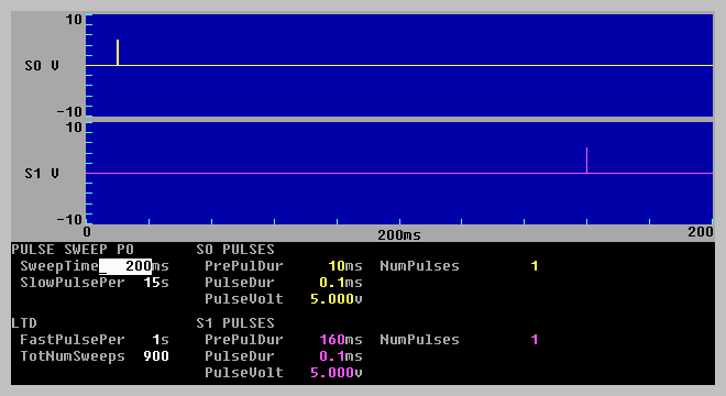
In another example with default start-up (no protocol file loaded), Fig. 3.1.2 shows paired-pulse stimulation and testing for Rm/Rs resistance where PulseSweep P0 has S0=Pulses, S1=None, Intracellular=Off, Digital=Off and Rm=On (see also the Stimulus Protocol Dialog Box, Fig. 3.4.1E). This would produce paired pulse S0 stimulation also with the intracellular test pulse for Rm/Rs measurement when the PulseSweep P0 train was elicited by pressing either Ctl-F5 or Ctl-F6.
Fig. 4.4.1 shows the full capability of the stimulation. S0 and S1 have Dual Trains, and Intracellular, Digital and Rm stimulations are On in the Stimulus Protocol Dialog Box.
Fig. 4.2.2 shows that pathway independence can be tested by comparing heterosynaptic paired pulse stimulation with one pulse on S0 and one pulse on S1 with the effects of homosynaptic paired pulse stimulation (see Fig. 3.1.2). Fig. 4.4.2 is produced by Pulses on both S0 and S1, and Intracellular, Digital and Rm stimulations are Off in the Stimulus Protocol Dialog Box. If the stimulation in Fig 4.2.2 is delivered as a 900 repetitive 1-2 Hz PulseSweeps, it can produce Long-Term Depression (see Otani, S. and Connors, J.A. Long-term depression of na�ve synapses in adult hippocampus induced by asynchronous synaptic activity. J. Neurophysiol. 73:2596-2601, 1997).
Fig. 4.4.3 shows a theta burst stimulation capable of inducing LTP. Only S0=Trains is on in the Stimulation Protocol Dialog Box, and just set the NumTrains greater than 1 to get repetitive train stimulation
Fig 4.4.4 shows Dual Train stimulation on S0. Only S0=DualTrains is on in the Stimulation Protocol Dialog Box. The three dual trains is set by setting the NumTrainLoops=3.
Fig. 4.4.5 shows primed burst stimulation capable of inducing LTP. Only S0=DualTrains is on in the Stimulation Protocol Dialog Box, only one three dual train is produced(by setting NumTrainLoops=1), and the first train has only one pulse (NumPulses=1).
Fig. 4.4.6 shows how intracellular stimulation can be coincident with extracellular pulse and train stimulation. In this example S0=DualTrains, and Intracellular and Rm stimulation are On in the Stimulus Protocol Dialog Box. In this example an intracellular depolarization occurs during the one priming S0 pulse, and hyperpolarization occurs during the S0 train. Intracellular voltage changes could have interesting effects on the ability of extracellular pulses and trains to induce LTP or LTD.
Fig. 4.4.7 shows a way of inducing LTD by generating a single, 3 minute long, 5Hz, 900 S0 pulse LTD stimulation sweep. Using a single long sweep with many pulses to get LTD stimulation is a way of ‘working around’ a limitation of LTP113E that allows usually only 1-2 Hz repetitive short stimulation sweeps on most Pentium and 486 computers. Note, however, that in LTP113E the number of S0 or S1 stimulus pulses per sweep is limited to about 1300.
After you have chosen your basic Stimulation Protocol in the Stimulation Protocol Dialog Box (Fig. 3.4.1E), then you have to set the Stimulation Field Values in TrainSweeps T0 and T1, and PulseSweeps P0 and P1. Experiment.
It is important to realize that there is a reciprocal relationship between the TrainSweep or PulseSweep ADinterval (see Fig. 3.1.6) and the maximum Sweep Time (see upper left field in Fig. 4.4.1) that is allowed. For instance, if we assume that a maximum of 100,000 samples/sweep (on an 8 MB computer) can be obtained, then if the PulseSweep ADinterval is set to 100 usec, then the maximum PulseSweep time will be 10 ssec. To extend the maximum PulseSweep time to 20 sec, the PulseSweep ADinterval must be increased to 200 usec. This is because the program always outputs an analog output voltage every 100 usec, but it may acquire a sample only every 100, 200 up to 50000 usec.
Therefore, it is important to understand that what you see in the Train and Pulse Stimulation graphs is what stimulus pulses you will generate. If you want to generate a repetitive stimulation and not all of it will ‘fit’ in the stimulation graphs, increase the ADinterval in the Miscellaneous Window. If not all of your stimulus pulses ‘fit’ in the stimulation graphs, no error message will be produced to tell you that. It is up to you to see that this doesn’t occur.
Finally, it is important to realize that extracellular S0 stimulation on the Digidata (AnalogOut0) and Labmaster (DA0) boards can also be either Monophasic or Biphasic. This is set by the Monophasic/Biphasic Extracellular Stimluation Dialog Box (Fig. 3.4.5D). Monophasic is the default condition, so that when the S0 PulseVolt is set to +5.0 volts and the PulseDur is set to 0.1 msec (see Fig. 4.4.3), then AnalogOut0 or DA0 produces a 0 to +5.0 volt pulse lasting 0.1 msec. However, if S0 is set to Biphasic, then when the S0 PulseVolt is set to +5.0 volts and the PulseDur is set to 0.1 msec, then AnalogOut0 or DA0 produces a 0 to +5.0 volt pulse lasting 0.1 msec which is followed by a -5.0 volts also lasting 0.1 msec before returning to 0 volts. When the PulseVolt is negative, a biphasic pulse would be first negative and then positive. The true S0 stimulus duration in the Biphasic mode is twice that stated in the PulseDur. Note that even though the Monophasic/Biphasic dialog box shows that S1 can be biphasic, this capability is not present in LTP113E.
Fig. 4.4.1. Full stimulation capability. This contains primed burst stimulation (S0) (e.g. one dual train), repeating dual trains (S1), digital sync output (DO0), digital pulse output (DO1, DO2) and intracellular (IC) epoch-like stimulation - also including the Rm/Rs pulse (on right). Note that the digital output can either be a sync pulse at the start of an epoch (produced by entering an ’S’ in the DigOut section), or a pulse lasting the whole epoch (produced by entering a ‘P’ in the DigOut section).
Fig. 4.4.2. Heterosynaptic paired-pulse stimulation can help test for pathway independence, or (when delivered as 900 1-2 Hz repetitive sweeps) can induce heterosynaptic LTD.
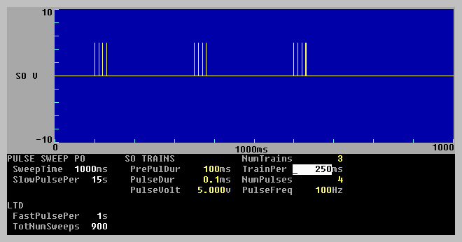
Fig. 4.4.3. Theta burst stimulation for LTP induction. Theta stimulation just consists of repeating single trains.
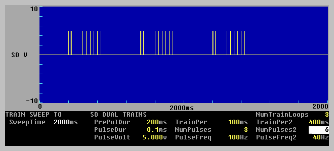
Fig. 4.4.4. Dual train S0 stimulation consisting of three dual trains (NumTrainLoops=3).
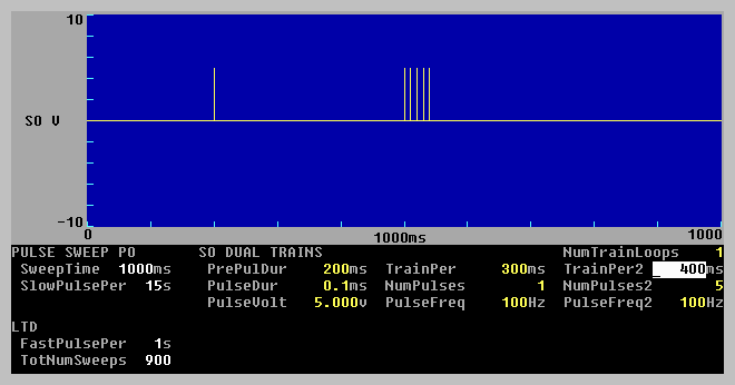
Fig. 4.4.5. Primed burst stimulation for LTP induction consisting of one dual train (NumTrainLoops=1) with the first train having only one pulse (NumPulses=1).
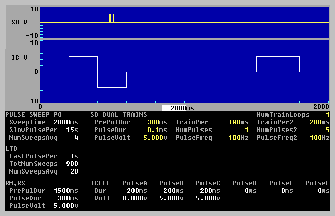
Fig. 4.4.6. Extracellular primed burst stimulation (S0) and coincident intracellular (IC) depolarization and hyperpolarization stimulation, an the Rm test pulse. Note that Signal Averaging was on for this protocol, e.g. NumSweepsAvg=4 for slow repetitive sweeps and NumSweepsAvg=20 for fast (LTD) repetitive sweeps.
Fig. 4.4.7. Fast (5 Hz) homosynaptic LTD stimulation using a single 3 min long sweep having 900 S0 pulses. Only the first 2000ms of the 180000ms sweep are shown.
4.5 Choosing the Waveform Calculations To Do
After setting the sweep stimulations, you have to decide which calculations you want to do. To do this call up the Amplitude/Slope Calculations To Do Dialog Box (Fig. 3.4.4C). On the right the dialog box shows which calculations can be done: DC Baseline of each PulseSweep, the Peak Amplitude, Peak Latency, Area, Duration, 10-90% Rise Time, 10-90% Decay Time, Coastline, PopSpike Amplitude, PopSpike Latency, Slope and/or Average Amplitude of synaptic potentials produced by S0 and S1 stimulation, and if the Rm pulse is On, cell resistance (Rm) and patch pipette series resistance (Rs).
The top line in the dialog box (under the title) shows where this calculations can be plotted or displayed. ViewPg determines whether none or one Calculation graph will be presented in the Main ViewPage Window. For example, a Slope calculation checked (‘X’ means On) produces a Slope Calculation graph in the Main ViewPage Window (see Fig. 3.1.4). More than one ViewPg calculations checked will not be accepted.
CalcPg0 and CalcPg1 determine which calculation graphs will appear on these pages, for example, Fig. 3.1.5 shows is the result when PeakAmp and Slope of CalcPg0 are checked. None to three calculations per CalcPg can be checked. More than three calculations will not be accepted. If no calculations are checked on a CalcPg, the CalcPg will not appear.
The CalcLine determines which calculation values from the last sweep will be presented on the Calculation Line. None to three calculations can be checked. More than three calculations will not be accepted.
If any of the locations (e.g. ViewPg, CalcPg0, CalcPg1 or CalcLine) appear on the calculations to do row (e.g. DC Baseline, Peak Amplitude, Peak Latency, Area, Duration, Rise Time, Decay Time, Coastline, PopSpike Amplitude, PopSpike Latency, Slope, Avgerage Amplitude, Rs and/or Rm), that calculated value will also be saved to the Amplitude/Calculation file (*.AM?) (see Section 4.7). Otherwise the value will be set to 0 in that file.
Note that although many S0 and S1 pulses can be generated in the PulseSweep and TrainSweep stimulations, only the first S0 pulse in PulseSweep P0 and the first S1 pulse in PulseSweep P1 are analyzed for Amplitude/Slope synaptic potential calculations. For example, if you want to analyze S0 and S1 pulses, have S0 pulses in PulseSweep P0 and S1 pulses in PulseSweep P1, not S1 only pulses in PulseSweep P0 and S0 only pulses in PulseSweep P1. The ability to analyze multiple extracellular S0 and S1 pulses in the PulseSweep has not been added yet, and no pulses can be analyzed in the TrainSweeps yet.
4.6 Setting the Calculation Detection Criteria
The fields that set the ranges for detecting the various calculations are set in the Pulse Waveform Detection Window (Fig. 3.1.3). However, only if at least one of the ViewPg, CalcPg0, CalcPg1 or CalcLine check boxes is chosen for a particular waveform calculation row in the Amp/Slope Calculations To Do dialog box (Fig. 3.4.4C) will the particular calculation be plotted and saved to the Amplitude/Calculation file as a non-zero value.
4.6.1. DC Baseline
If DC Baseline, Peak Amplitude, Peak Latency, Area, Duration, Rise Time, Decay Time, Average Amplitude, or Slope (for Low% -> High% Peak Amplitude) is chosen, then the DC Baseline value will be calculated.
The
BaselineS0: __ to __ms before pulse
time fields shown in the Pulse Detection Window (Fig. 4.6.1) set the pre-stimulus pulse baseline to be between these two ‘Baseline’ time values, and both are relative to the stimulus pulse.
4.6.2 Peak Amplitude and Peak Latency
The Peak Amplitude is the difference between the DC Baseline value and the calculated peak. The peak will be measured between the time fields in
Peak: ___ to ___ms after pulse A/P/N:_
and is shown by the PkAmp solid line of the Pulse Detection Window (Fig. 4.6.1). The first ‘Peak’ time value must be before the Peak Amplitude, and the second ‘Peak’ time value must be after the Peak Amplitude, and both are relative to the stimulus pulse.
The A/P/N field determines whether the peak will be Automatically (A) determined to be positive or negative, forced to be Positive (P), or forced to be Negative (N). The normal value is A, automatic. Automatic calculates whether the average of the points between the Peak: ___ to ___ms after pulse time fields is more positive than the baseline average value. If so, the peak is positive; otherwise the peak is negative.
Peak Latency is the time between the occurrence of stimulus pulse and the peak.
4.6.3 Slope
The Slope is calculated by taking all the waveform voltage/current points from the slope beginning time point to the slope end time point, and using these points to calculate a linear regression line (least squares fit) through the data.
When analyzing the Slope of the EPSP/EPSC there are two ways to determining the slope beginning time point and the slope end time point. These Slope Calculation Methods are chosen by using the menu commands (Fig. 3.4.4.A):
AmpFile -> Slope calculation method...
to bring up the Slope Calculation Methods dialog box with the following choices (Fig. 3.4.4G).
| ( ) Begin -> End Times | ||||
| ( ) Low% -> High% Peak Amplitude |
The first method, the begin -> End Times, is to merely set the slope beginning time point and the slope end time points. If this method is chosen (and this is the default method), the Pulse Detection Window appears as in Fig. 4.6.1. The slope beginning and end time points are the time fields:
Slope: ___ to ___ms after pulse
The second method, the Low% -> High% Peak Amplitude calculates the slope beginning time point by using the time where the voltage/amperage was say 20% (the Low%) of the Peak Amplitude value. It calculates the slope end time point by using the time where the voltage/amperage was say 80% (the High%) of the Peak Amplitude value. If this method is chosen, the Pulse Detection Window appears using the following fields:
Slope: ___ to ___% peak amplitude
where the first % field is the Low% field and the second % field is the High% field.
Both methods have their advantages. If the latency between the stimulus pulse and the slope shifts with time, the Low% -> High% Peak Amplitude method is best. However, when the EPSP/EPSC amplitude approaches 0, the Low% -> High% method begins to calculate slopes made of noise and therefore gives spurious result. In contrast, the Begin -> End Times method continues to accurately measure the slope when the EPSP/EPSC amplitude approaches 0. In general, because the latency of the EPSP/EPSC normally does not change much, and because the amplitude of an EPSP/EPSC can often go to 0, the , the Begin -> End Times is usually the method of choice and is the default value.
Slope detections in our group are usually of 0.6 to 2.0 msec duration. When sampling every 100 usec, this is 7 to 21 AD samples, respectively. Obviously the longer the slope duration the better, provided the slope still remains on the ‘straight’ part of the EPSP/EPSC. On-line signal averaging also decreases slope error measurement.
I have been particularly concerned that the AD sample-to-sample time jitter (on the order of 2-7 usec, APPENDIX A.6) could affect the slope measurement. However, this jitter is essentially random, and I think that the random sample-to-sample jitter would essentially add white noise to a sloped voltage or current acquired with no sample-to-sample jitter. Because a linear regression (least squares fit) line is calculated for these points, the sample-to-sample jitter should have very little effect. By comparison, it is obvious when analyzing/reanalyzing data that any 50/60 Hz line noise in the signal clobbers an accurate slope measurement.
Finally, check that the slope calculation is working correctly. Now that the basic acquisition, stimulation and amplitude and slope calculations have been performed it is important to double check that the slope calculations are working correctly. To check that the slope calculated by the LTP113E program are correct, input a ramp or triangle waveform from a waveform generator. See if the LTP113E program gives the correct slope calculations compared to what you know is being output (which can be independently checked with an oscilloscope). Make sure your waveform generator has very low noise. (See Section 2.8.)
4.6.4 Area
Area calculates the area of the peak more negative or positive than the pre-pulse DC Baseline and is measured in mV*ms or pA*ms. The Area is measured between the
Peak: ___ to ___ms after pulse A/P/N:_
time fields shown by the solid horizontal Area line of the Pulse Detection Window (Fig. 4.6.3). Just as with the Peak Amplitude measurement, the A/P/N field determines whether the peak will be Automatically (A) determined to be positive or negative, forced to be Positive (P), or forced to be Negative (N).
Notice, that when the waveform goes to the opposite polarity of the peak, those values are not calculated in the area (for example, in Fig. 4.6.3, when the waveform goes positive after 16 ms, the area is only between the first ‘Peak’ time field and up to 16 ms after the pulse.
4.6.5 Duration
Duration calculates the duration of the peak or peaks measured between the
Peak: ___ to ___ms after pulse A/P/N:_
time fields shown by the dotted horizontal peak line in the Pulse Detection Window (Fig. 4.6.4). Just as with the Peak Amplitude measurement, the A/P/N field determines whether the peak will be Automatically (A) determined to be positive or negative, forced to be Positive (P), or forced to be Negative (N).
The Duration is measured at a certain percentage of the amplitude between the DC baseline and peak
Dur: ___% of peak
and is shown by the solid line between the arrows in Fig. 4.6.4.
Duration can measure the duration of bursts (multiple spikes or peaks), and is therefore particularly useful in epilepsy studies for measuring the duration of epileptiform bursts and electrographic seizures.
4.6.6 10-90% Rise Time and 10-90% Decay Time
Rise Time calculates the time between 10% and 90% of DC baseline to peak on the rising phase of the peak and is shown by + ‘s. Decay Time calculates the time between 10% and 90% of DC baseline to peak for the falling phase of the peak and is also shown by + ‘s. Therefore the Rise Time and Decay Time depend on DC baseline settings. The Rise Time and Decay Time is measured between the
Peak: ___ to ___ms after pulse A/P/N:_
time fields shown by the dotted horizontal peak line in the Pulse Detection Window (Fig. 4.6.5). Just as with the Peak Amplitude measurement, the A/P/N field determines whether the peak will be Automatically (A) determined to be positive or negative, forced to be Positive (P), or forced to be Negative (N).
4.6.7 Coastline
Coastline calculates the amount of vertical deflection between the
CoastLn: ___ to ___ms after pulse
time fields and is shown to occur between the left and right brackets on the waveform (Fig. 4.6.6). (Alternatively, if Peak Amplitude is also being calculated, Peak: ___to ___ms after pulse A/P/N:_ indicates the time fields). The Coastline is measured in mV or pA. Coastline does not depend upon DC baseline or Peak Amplitude.
Coastline is indicative of, and sensitive to, the addition of extra population spikes in an epileptiform burst and can therefore be useful in epilepsy studies.
However, coastline will also increase with extraneous high frequency noise and you should be sure that sufficinet external analog or internal digital filtering (Section 5.3) is applied to the waveform when the Coastline measurement is made.
4.6.8 PopSpike Amplitude and PopSpike Latency
There are two ways to calculate the PopSpike Amplitude and Latency: the Autodetection method and the Manual method. These PopSpike Calculation Methods are chosen by using the menu commands (Fig. 3.4.4.A):
AmpFile -> PopSpike calculation method...
to bring up the PopSpikee Calculation Methods dialog box with the following choices (Fig. 3.4.4H).
| ( ) Tangent Autodetection | ||||
| ( ) Manually set three peaks |
In the Tangent Autodetection method (which is the defalult method), the PopSpike Amplitude is calculated as the amplitude from the popspike peak to the intersection with an interpolated tangent dotted line drawn between the pre-popspike peak to the post-popspike peak (shown be the solid vertical line in Fig. 4.6.7). PopSpike Latency is calculated as the time between the occurrence of stimulus pulse and the popspike peak. PopSpike Amplitude and PopSpike Latency do not depend upon DC baseline or Peak Amplitude.
In order to use the Tangent Autodetection method correctly you must first set the popspike to be negative or positive by setting the P/N field in
PSamp: ___ to ___ms after pulse P/N:_
(If Peak Amplitude it to be calculated then the above line is just PSamp: P/N:_ .)
Next, you must set the time range the popspike will be detected over by the "__to__ms after pulse" fields above. (If Peak Amplitude it to be calculated then use the time fields in the "Peak:__to__ms after pulse A/P/N:_" .) This time range is shown between the left and right bracket located on the waveform in Fig. 4.6.7.
Alternatively, you can use the Manual detection method to manually set the three peaks as in the following line
PSamp: ___, ___, ___ +- ___ms
where the first three fields are the times of the three peaks, and the fourth field determines the width of each peak to be include in their average amplitude.
The Manual detection method should only be used with those rare waveforms where the Autodetection method does not work.
4.6.9 Average Amplitude
The Average Amplitude is the difference between the DC Baseline value and the averaged values between the
AvgAmp : ___ to ___ms after pulse
time fields and is shown in the AvgAmp solid line of the Pulse Detection Window (see Fig. 4.6.8).
4.6.10 Cell Resistance (Rm)
Cell resistance (Rm) detection occurs automatically. The Rm measurement is the difference between the averaged PreRmBaseline and the averaged RmPulse. That part of the Rm measurement taken during the RmPulse is an average taken between 50% and 90% of the RmPulse. That part of the Rm measurement taken during the PreRmBaseline is taken between 10% and 90% of that period, or a maximum duration of the time equal to 50-90% of the RmPulse.
Note that the Cell Resistance, Rm, is actually the amplitude of the voltage or current deflection during the current injection pulse when stimulating intracellularly. It is measured in mV or pA and is therefore only an indirect measurement of Cell Resistance that can be obtained by Rm = Vm / ISteadyState.
4.6.11 Patch Electrode Series Resistance (Rs)
The patch electrode series resistance (Rs) can either be taken as the 1) peak of the capacitative transient, 2) the extrapolated peak fitted by a single exponential, or 3) the extrapolated peak fitted by a double exponential.
Unfortunately, the exponential fitting is still a work in progress. The code appears to be fine, but in practice we have found that this double exponential fit (which is a better fit for a hippocampal cell than a single exponential) can be variable due to the relatively slow AD sampling interval of 100 usec in LTP113E, and therefore may not be dependable. Whether the fit is dependable depends to a certain extent on what is recorded. You have to test out the dependability for yourself. Future versions of the LTP program will have to have substantially higher sampling frequency of 10-20 usec in order for Rs exponential fitting to work well.
Instead, we find that the most accurate determination of Rs is to measure an unfiltered Rs peak on the on-line oscilloscope at various times during the experiment, and use the Rs peak measurement made by the LTP program to detect if there is a change in true Rs. This assumes that you have cancelled out the pipette capacitance.
Note that for all three ways to measure the patch electrode series resistance (Rs) is actually the peak or fitted amplitude of the capacitative transient and is measured in pA. Rs must be manually converted to resistance by Rm = Vm / IPeak.
The method of determining patch electrode series resistance (Rs) is chosen by using the menu commands (Fig. 3.4.4.A):
AmpFile -> Rs calculation method...
to bring up the Series Resistance Calculation Methods Dialog Box (Fig. 3.4.4F). The top of the dialog box gives the following choices to choose the method of Rs calculation:
| Series Resistance (Rs) Calculation Method |
| ( ) Peak | ||||||
| ( ) Single exponential decay fit | ||||||
| ( ) Double exponential decay fit |
If the Peak Rs detection method is chosen, no fields need to be entered. For this value to be even proportionally related to the true Rs value, make sure you have canceled out the pipette capacitance.
If the Single exponential decay fit Rs detection method is chosen, the fit is taken between these times after the Rm pulse has stared:
RsExpFit: ___ to ___ms after Rm start
and the calculated Baseline, Coefficient0 and Tau0 are presented by the following values:
Baseln=___pA C0=___pA Tau0=___ms Er=_____ NI=__
and where Er is the Total Squared Error and NI is the Number of Iterations required for the fit to be reasonably accurate. This is according to the following formula:
F(t) = Baseln + C0 * exp(-t/Tau0)
If the Double exponential decay fit Rs detection method is chosen, then you have to decide whether you want to automatically seed or manually seed the double exponential decay fit and choose this from the bottom of the Series Resistance Calculation Method Dialog Box (Fig. 3.4.4G):
| Seeding Double Exponential Curve Fit |
| ( ) Auto Seed | ||||||
| ( ) Manual Seed |
With both methods you again choose to fit between these times after the Rm pulse has started (see Figs. 4.6.9 and 4.6.10):
RsExpFit: ___ to ___ms after Rm start
However, if you have elected the Manual Seed (and the Auto Seed rarely works), you have to choose reasonable values for and the Baseline, Coefficient0, Tau0 and Coefficient1, Tau1 which are entered on the following line:
Baseln=__pA C0=__pA Tau0=__ms C1=__pA Tau1=__ms
and the calculated Baseline, Coefficient0, Tau0 and Coefficient1, Tau1 are fitted by the following values:
Baseln=__pA C0=__pA Tau0=__ms C1=__pA Tau1=__ms Er=__ NI=__
and Er where is the Total Squared Error and NI is the Number of Iterations required for the fit to be reasonably accurate. This is according to the following formula:
F(t) = Baseln + C0 * exp(-t/Tau0) + C1 * exp(-t/Tau1)
For a discussion on the correct measurement of Series Resistance using exponential curve fitting see Ogden and Stanfield (Patch clamp techniques for single channel and whole-cell recording, In: Microelectrode Techniques, The Plymouth Workshop Handbook, Second Edition, Ed. D. Ogden, The Company of Biologists Ltd., Cambridge, 1994).
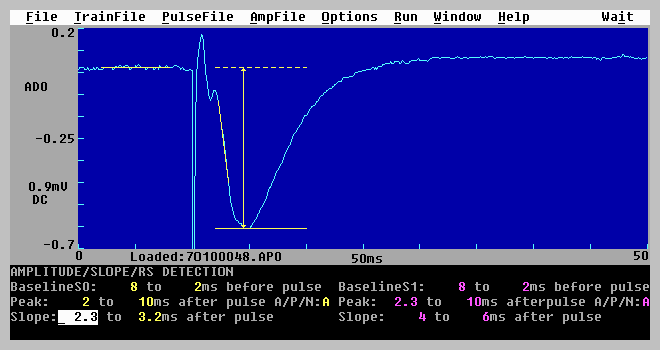
Fig. 4.6.1 Detection of extracellular synaptic waveform parameters (DC Baseline, Peak Amplitude and Slope). This data was acquired using a Pico board. (Data courtesy of Nicola Kemp and Zafar Bashir.)
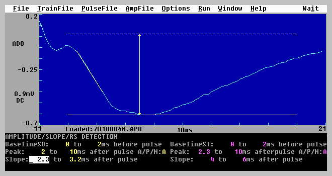
Fig. 4.6.2. Detection of synaptic waveform parameters at a magnified sweep timebase for a more accurate setting of detection parameters (same sweep as Fig. 4.6.1).
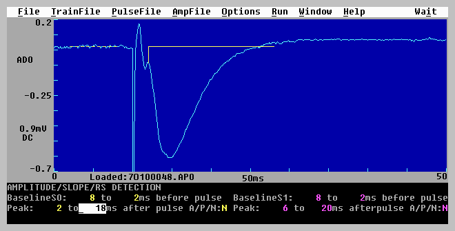
Fig. 4.6.3. Detection of Area of the peak more negative than the pre-pulse baseline. The Area is measured in the range of 2 and 18 ms after the stimulus pulse (solid horizontal line). However, because the waveform goes positive at 16 ms, the area is only measured between 2 and 16 ms after the pulse.
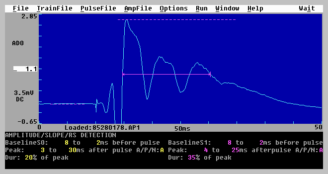
Fig. 4.6.4. Detection of Duration in the range of 4 and 25 ms after the stimulus pulse (dotted line). The Duration is measured at 35% of the peak amplitude and is between the arrows (solid line). The duration of bursts can be measured.
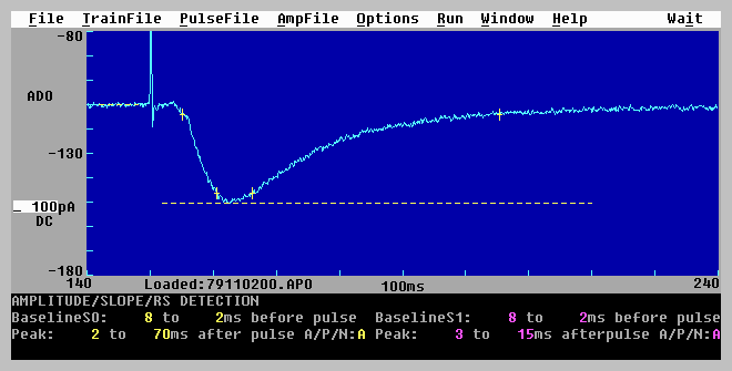
Fig. 4.6.5. Detection of 10-90% Rise Time and 10-90% Decay Time. The 10% and 90% Rise Times are denoted by the first and second + ‘s. The 10% and 90% Decay Times are denoted by the third and fourth + ‘s. The range for detecting the Rise and Decay Times (shown by the dotted line) was set to 2 to 70 ms after the stimulus pulse.
Fig. 4.6.6. Detection of Coastline. The Coastline is measured between the left and right bracket located on the waveform.
Fig. 4.6.7. Detection of Population Spike Amplitude and Population Spike Latency. Detection occurs between the left and right brackets on the waveform. The solid vertical line is the PopSpike Amplitude, and the time between the stimulus pulse and the solid vertical line is the PopSpike Latency.
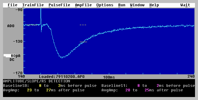
Fig. 4.6.8. Detection of Average Amplitude between 23 and 27 ms after the stimulus pulse (solid line) relative to the pre-pulse baseline (dotted line).
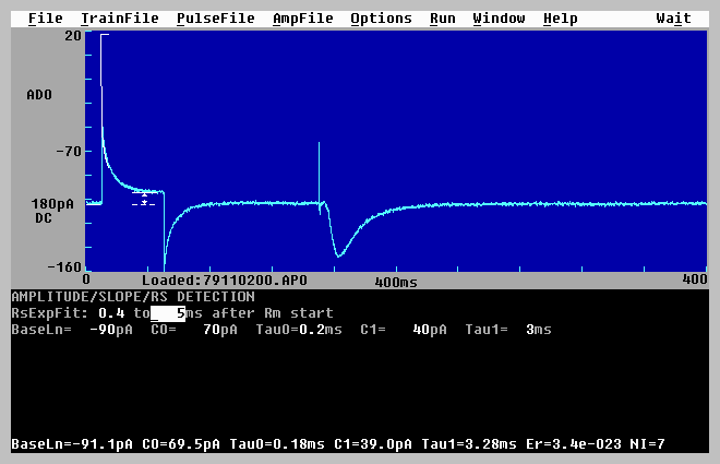
Fig. 4.6.9. Detection of patch electrode series resistance (Rs) and cell resistance (Rm) in a patch clamp recording during Rm pulse stimulation (left of trace). (Rs and Rm are actually measured in pA’s and manually converted to resistance by R=V/I). (Data courtesy of John Isaac and Graham Collingridge.)
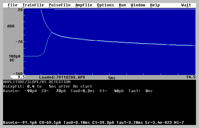
Fig. 4.6.10. High magnification timebase of the initial transient caused by the Rs/Rm pulse (same sweep Fig. 4.6.9). A double exponential curve has been fitted to the Rs transient to extrapolate to the beginning of the Rs/Rm pulse (at 10.0 ms). The double exponential has been manually seeded.
4.7 AutoReset Timebase (AutoZoom)
Sometimes when the sweep time is full scale, it is not clear how well the linear regression Slope line fits the synaptic potential, or how well the Rm/Rs pulse current transient is exponentially fitted because the synaptic potential or Rm/Rs pulse current transient is too small a portion of the ADsweep. If this is the case, synaptic potential or Rm/Rs transient can be zoomed in on by using the menu command (Fig. 3.4.5A):
Options -> AutoReset ADsweep timebase...
to call up the AutoReset dialog box (Fig. 3.4.5B) which gives the following choices
| AutoReset ADsweep to full timebase (MinTime->0, SweepTime->Full) |
| ( ) On | ||||||
| ( ) Off |
In the default condition when AutoReset ADsweep timebases is set to On, the beginning ADsweep time returns to 0 every time a new ADsweep is acquired or loaded, and the ADsweep duration is sent to the full time available every tune a new ADsweep us acquired or loaded.
However if AutoReset ADsweep timebases is set to Off, the beginning ADsweep time and the ADsweep duration remain at the zoomed in values every time a new ADsweep is acquired or loaded. Fig. 4.6.2 shows the loading of an ADsweep with AutoReset ADsweep timebases set to Off. In this case the start of the ADsweep graph begins 11 msec after the acquisition has begun, and the ADsweep graph duration is only 10 msec of the total 50 msec acquisition time.
While the experiment is in progress, or during reanalysis, you can toggle back and forth between full and zoomed time sweeps of the graph by using the menu command (Fig. 3.4.5A)
Options -> Toggle full/zoomed ADsweep timebase...
4.8 Setting which Files to Saved
Go to the last ‘Miscellaneous’ Window (Fig. 3.1.6) using either PgDn or the menu (Fig. 3.4.7)
Window -> 6 Miscellaneous
To save the Train ADsweep data for possible later reanalysis or plotting MAKE SURE the AutoSave PulseSweep->disk field is set to ‘Y’ (yes), as shown below (see Fig. 3.1.6):
| SAVING TRAIN DATA |
| AutoSave PulseSweep -> disk | Y |
If you want to save the Pulse AD sweep files for possible later reanalysis or plotting (and you almost always want to save this data!!) MAKE SURE the AutoSave ADsweep->disk field is set to ‘Y’ (yes). Unless you want to do an on-line plotting of each AD sweep, set the AutoSave ADsweep->printer field is set to ‘N’ (no), as shown below (again see Fig. 3.1.6):
| SAVING PULSE DATA |
| AutoSave PulseSweep | -> disk | Y | ||||||||
| -> printer | N |
If you want to save the Amplitude/Slope calculation data to the *.AM0 or *.AM1 files (and you almost always want to save this data on-line, although you can go back and reanalyze it if you’ve saved the original ADsweeps) MAKE SURE the ALL the AutoCalc and AutoSave Amp/Slope values->disk fields are set to ‘Y’ (yes), as shown below:
| SAVING AMPLITUDE/SLOPE DATA |
| AutoCalc Amp/Slope values | Y | ||||||||
| AutoSave Amp/Slope values -> disk | Y |
Note that the number of AD sweep files that can be handled is usually 10000 files, although only 5000 files may be handled on some computers with 8 MB of memory. We have found (at least on 486 computers with Windows 3.1 and DOS 6.0) that with more than 3000 ADsweep files per directory, saving and reloading slows down.
4.9 Saving the Protocol (*.pro) File to Disk
After changing any of the values in the program that determine the type of protocol, the stimulation or acquisition parameters, the graph axes values, etc., these values can then be saved to disk by using the menu commands (Fig. 3.4.1A):
File -> Save As
To open the Protocol File SaveAs Dialog Box (Fig. 3.4.1C). If the protocol file is to be saved under a different name, and then enter the filename - any filename ending in pro, such as "sigavg.pro".
If the file is just to be updated save it as use the menu commands:
File -> Save
Updating the protocol file is very useful in resuming the experiment if a crash or power outage has occurred (see Section 4.14).
4.10 Run the Experiment
Choose the appropriate protocol to run by using the run menu, for example (Fig. 3.4.6)
Run -> Protocol … CTL-F6
would mean pressing Alt-R and then ALT-P or just ‘p’. Alternatively press the CTL-F6 function key combination to begin running the protocol.
The LTD protocol can be run by pressing CTL-F7 or CTL-F11. The produces a Pulse stimulation and acquisition to occur every:
FastPulsePer __s
with a:
TotalNumSweeps __
and if averaging is on:
NumSweepsAvg __
as shown in the Pulse S0 Stimulation Window (see Fig. 4.4.6).
There can be some ADsweep-to-sweep jitter during rapid LTD stimulation (see APPENDIX A.9). Measure this sweep-to-sweep jitter on your computer, and if the jitter is too large, do your LTD stimulation with an auxiliary stimulator.
4.11 Printing AMP Graphs, ADsweep Graphs and AMP Text Files After an Experiment
Printing out AMP graphs, ADsweep graphs, and AMP text files is usually done at the end of an experiment. However, it can also be done on-line during the experiment if a printer is directly connected to your data acquisition computer (or the printer is connected to a networked computer, see Section 6.1).
The linewidth of both the Amp/Slope graphs and the ADsweep graphs on the LaserJet printer can also be changed from 1 to 10 dots (at 300 dots/inch resolution) by using the commands:
Options -> HP LaserJet linewidth ...
and then entering a number in the field between 1 and 10 (Fig. 3.4.5G). See Fig. 4.11.3 for ADsweep graphs with lines of of 1,3,5 and 7 dot widths.
4.11.1 AMP Graphs
To print out the Amplitude/Slope calculation graphs (DC Baseline, Peak Amplitude, Slope, Average Amplitude, Rm and/or Rs) at the end of the experiment, but before LTP113E is exited, use the menu commands (Fig. 3.4.4A):
AmpFile -> Plot on printer/plotter
Alternatively, if a printer/plotter is not directly connected to your computer, you can "plot" the Amplitude/Slope calculation graphs to a HP LaserJet compatible file by using the menu command:
AmpFile -> "Plot" to graph File
Later after LTP113E is exited, you can then copy the graph files to a HP LaserJet printer by using the command from the DOS command line using either of the following commands (the Amp/Slope graph file name is 8704A000.LJ0 for example):
| C:\YOURDATA\980704> copy 8704A000.LJ0 prn | ||||
| or | ||||
| C:\YOURDATA\980704> type 8704A000.LJ0 > prn | ||||
| or | ||||
| C:\YOURDATA\980704> ljprint 8704A000.LJ0 |
An example of printing Amp/Slope graphs to a LaserJet printer from a *.LJ0 graph file is shown in Fig. 4.11.1.
4.11.2 ADsweep Graphs
To plot a AD PulseSweep file to the printer during or after the experiment use the menu commands:
PulseFile -> Plot on printer/plotter
Alternatively, if a printer/plotter is not directly connected to your computer, you can "plot" the AD PulseSweep to a graph file by using:
PulseFile -> "Plot" to graph File
Later after LTP113E is exited, you can then copy them to a HP LaserJet printer by using the command from the DOS command line using either of the following commands (the graph file name containing the AD sweep(s) is 87040000.LJ for example):
| C:\YOURDATA\980704> copy 87040000.LJ prn | ||||
| or | ||||
| C:\YOURDATA\980704> type 87040000.LJ > prn | ||||
| or | ||||
| C:\YOURDATA\980704> ljprint 87040000.LJ |
You can plot up to 4 ADsweeps on one page (default values) but this can be changed using the menu commands (Fig. 3.4.5A):
Options -> HP LaserJet chart layout ...
and choosing from 1 to 9 charts per page with various x/y aspect ratios from the LaserJet Chart Layout Dialog Box (Fig. 3.4.5F).
Note: it is presently not possible to directly plot AD TrainSweeps during an experiment. However, you can do so after an experiment by loading the TrainSweep file into the PulseSweep array by using the commands:
PulseFile -> Open
An example of printing one ADsweep graph per page of a patch clamp experiment to a LaserJet printer from a *.LJ graph file is shown in Fig. 4.11.2. An example of printing 4 ADsweep graphs of extracellularly recorded field EPSPs to a LaserJet printer from a *.LJ graph file is shown in Fig. 4.11.3. The linewidth of each sequential graph as been changed from 1 to 3 to 5 to 7 dots (300 dots/inch).
4.11.4 AMP ASCII Text Files
Later after LTP113E is exited (or while LTP113E is running by going to the DOS command line File->DOS command line, Fig. 3.4.1A) , you can also copy the AMP text files (*.AM0 or *.AM1) themselves to a HP LaserJet printer at the DOS command line by using the following commands (the AMP text file name containing the Amplitude/Slope/Rm calculations is 8704A000.AM0 for example) (C:>copy 8704A000.AM0 prn, or C:> type 8704A000.AM0 > prn).
However, usually the AMP text files are directly loaded into a spreadsheet program such as Excel, or plotting program such as Sigma Plot.
An example of the structure of an AMP text file is shown in Fig. 4.11.4.
4.11.5 ADsweep ASCII Text Files
Although you normally do not want to directly examine the ADsweep ASCII text files, the header and the first 5 data points of an ADsweep file are shown in Fig. 4.11.5. This will be helpful if you want to write a custom program to do different analyses of the ADsweep files than is available in LTP113E.
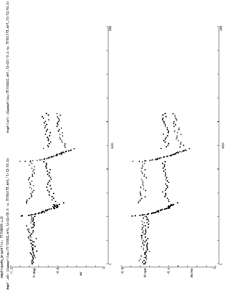
Fig. 4.11.1. (Next Page) An example of printing Amplitude/Calculation graphs to a LaserJet printer from a *.LJ0 graph file. (To print Figs. 4.11.1, 4.11.2 and 4.11.3 in this manual I used IMSI Graphics Converter Gold to convert the *.LJ file to a BitMap (*.BMP) file.
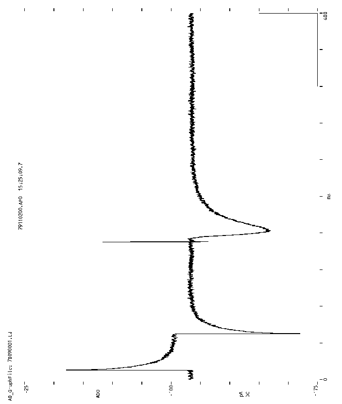
Fig. 4.11.2. Printing one ADsweep graph per page of a patch clamp recorded current injection pulse (left) and an EPSC (middle) to a LaserJet printer from a *.LJ graph file.
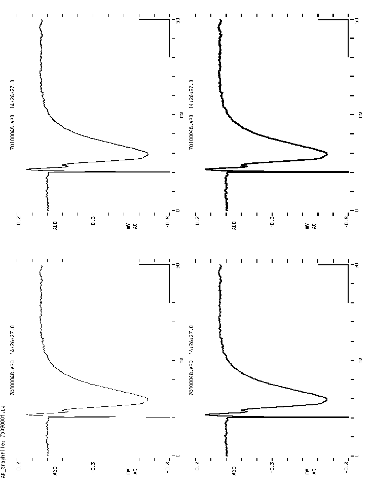
Fig. 4.11.3. (Previous Page) Printing four ADsweep graphs per page of extracellularly recorded field EPSPs to a LaserJet printer from a *.LJ graph file. The linewidth of each sequential graph as been changed from 1 to 3 (default) to 5 to 7 dots (300 dots/inch).
| "Amp_Filename" "7515R000.AM0" | |
| "Analysis_or_Reanalysis" "Offline_Reanalysis" |
| "#" | "Filename" | "TimeOfDay" | "Time(min)" | "DC_mV" | "PkAmp_mV" | "PkLat_ms" | "Ar_mV*ms" | "Dur_ms" | ||
| 0 | "75150003.AP0" | "12:02:55.0" | 0.000 | 0.208 | -0.928 | 0.0 | 0.000 | 0.000 | ||
| 1 | "75150004.AP0" | "12:04:55.0" | 2.000 | 0.208 | -0.934 | 0.0 | 0.000 | 0.000 | ||
| 2 | "75150005.AP0" | "12:06:55.0" | 4.000 | 0.220 | -0.922 | 0.0 | 0.000 | 0.000 | ||
| 3 | "75150006.AP0" | "12:08:55.0" | 6.000 | 0.214 | -0.916 | 0.0 | 0.000 | 0.000 |
| "RisTm_ms" | "DecTm_ms" | "CstLn_mV" | "PSamp_mV" | "PSlat_ms" | "Sl_mV/ms" | "AvAmp_mV" | "Rs_mV" | "Rm_mV" | ||
| 0.000 | 0.000 | 0.000 | 0.000 | 0.0 | -0.610 | 0.000 | 0.000 | 0.000 | ||
| 0.000 | 0.000 | 0.000 | 0.000 | 0.0 | -0.620 | 0.000 | 0.000 | 0.000 | ||
| 0.000 | 0.000 | 0.000 | 0.000 | 0.0 | -0.647 | 0.000 | 0.000 | 0.000 | ||
| 0.000 | 0.000 | 0.000 | 0.000 | 0.0 | -0.639 | 0.000 | 0.000 | 0.000 |
Fig. 4.11.4 The first four sweeps of an Amplitude/Calculation ASCII text file. The actual file is 18 columns wide but had to be separated into two sections to fit on the page. Only DC, PkAmp and Slope were calculated, the other values were not calculated and were set to 0.
| "ASF" | "0.90F" |
| "DataFileName" | "75150003.AP0" |
| "UserName" | "No_specified_username" |
| "DateFileSaved" | 970515 |
| "TimeFileSaved" | "12:02:55.0" |
| "TimeSavedMidnight" | 43375.0 |
| "GroupNum" | 0 |
| "SweepNum" | 0 |
| "AD0_ChNum" | 15 |
| "AD0_DataType" | "mV" |
| "AD0_Gain" | 1000.000 |
| "AD0_DigFilter_Hz" | 0 |
| "NumSamples1" | 1000 |
| "SampleInterval1_ms" | 0.1 |
| "PreRmPulseDur_ms" | 0 |
| "RmPulseDur_ms" | 0 |
| "RmPulseAmp_v" | 0.000 |
| "PreStimPulseDur_ms" | 10 |
| "StimPulse_S0_v" | 5.000 |
| "StimPulse_S1_v" | 0.000 |
| "mV" | |
| 0.2197 | |
| 0.2136 | |
| 0.2075 | |
| 0.2075 | |
| 0.2136 |
Fig. 4.11.5 The header and first five samples of an ADsweep ASCII data file. ADsweep files can also be saved in two columns of data, time (in ms) and amplitude in pA, mV etc.
4.12 Zipping and Saving Data Files at the End of an
Experiment
At the end of the experiment you may decide to compress all your ADsweep data files (*.T0, *.T1, *.P0, *.P1, *.AP0, *.AP1), Amplitude/Calculation files (*.AM0, *.AM1) and HP LaserJet graphic files (*.LJ?) in your days data directory into one zipped file by using ZIPMAGIC, WINZIP, PKZIP or other file compression program. The decision to zip is influenced by size and cost of backup media versus ease of reanalysis (files may have to be unzipped for reanalysis). For example, data files archived onto floppies are usually zipped, whereas data files archived onto a writeable CD-R may not be zipped.
The most interesting zip program is ZIPMAGIC. ZIPMAGIC: 1) allows you to treat a Zip file like a Zip folder while in the Windows Explorer, My Computer etc. You can easily move files in and out of the Zip File/Folder, and easily delete files. 2) More amazing, you dont have to unzip a Zip File/Folder to load a file into another Windows program like NotePad or SigmaPlot! The File->Open dialog box in these programs understands its a Zip File/Folder!!! 3) Even more amazing, if you go into the DOS compatibility box, the Zip file becomes a Zip directory, you can change to the Zip File/Directory, and you can load and save zipped files with some DOS programs like Edit.com. 3) But most amazing, if you go into the DOS compatibility box, the Zip file becomes a Zip directory, and you can run LTP113E to reanalyze unzipped ADsweep files. Note however, that you cannot run ZIPMAGIC in Real DOS and therefore cannot use it during LTP113E data acquisition.
The only problem we have found with ZIPMAGIC is that it can be very slow if the zipped file/folder contains a large number of ADsweep files (say 3000) that are fairly large (say 20,000 samples/file). Anyways, definately check out ZIPMAGIC at www.zipmagic.com.
4.12.1 Zipping Files with PKZIP
If you want to zip your files using the DOS PKZIP program, the following command line compresses all the files in the 980704 directory into one file, 980704.ZIP:
C:\YOURDATA\980704> pkzip 980704 *.*
The file contents in the 980704.ZIP file can be viewed by using the command:
C:\YOURDATA\980704> pkzip -v 980704
To again use the files, unzip them with PKUNZIP.EXE. The following command line extracts or unzips all the files from 980704.ZIP:
C:\YOURDATA\980704> pkunzip 980704
To extract only a certain group of files from 980704.ZIP, say all Amplitude/Slope files with AM0 extensions, and two AD waveform files 87040111.A0 and 87040222.A0, use the following command line:
C:\YOURDATA\980704> pkunzip 980704 *.AM0 87040111.A0 87040222.A0
See the PKZIP manual for more details or type PKZIP at the command line to get an abbreviated explanation of what else to do. PKZIP is one of the standard file compression program for Microsoft/Intel PCs. I have used PKZIP for years without a single problem.
Generally it is a wise decision to save the ADsweep files (*.T0, *.T1, *.P0, *.P1, *.AP0, *.AP1), the Amplitude/Calculation files (*.AM0, *.AM1), and the LaserJet files (*.LJ?) to two other sources, 1) on the hard disk of one other computer and 2) to either an optical disk or a writable CD-R. I have yet to find a method of backup that is completely error free - including optical and CD-R disks. Also, you might delete the space consuming ADsweep files (*.T0, *.T1, *.P0, *.P1, *.AP0, *.AP1) from the hard disk of your data acquisition computer if more space is needed, but keep all the smaller Amplitude and LaserJet files (*.AM0, *.AM1 and *.LJ?) on your hard disk.
4.12.2 The Amount of Space Saved by Zipping Your Files
You should realize that the amount of bytes a data file takes up on hard disk or CD-R may be much larger than the number of bytes in these files. For data acquisition programs such as LTP that save many small files rather than one large file, it may be very useful to zip the data. For example, the Reanalysis Dialog Box (Fig. 3.4.4B) shows 250 Averaged PulseSweep (*.AP0) files. Each of these files contains 500 samples, which when saved as an ASCII text file along with the header information takes up about 4,632 bytes (about 8 to 9 bytes or characters per sample). However, the actual disk space it uses on this 2 gigabyte disk is 32,768 bytes (the minimum file size for the cluster size of a 2 gigabyte disk with a 16-bit FAT). (On a 1 gigabyte hard diskwith a 16-bit FAT, the minimum file size is 16,384 bytes, and on an 8 gigabyte hard disk with a 32-bit FAT, the minimum file size is 8192 bytes.)
Therefore, although there were only 1,165,568 bytes in the 250 Averaged PulseSweep (*.AP0) files, they took up 8,192,000 bytes!. Furthermore, after these 250 Averaged PulseSweep (*.AP0) files were zipped, the zip file had only 235,738 bytes in it and took up on 262,144 bytes on the hard disk.
Comparing 1,165,568 bytes to 235,738 bytes shows an 80% reduction in the number of bytes in these files. However, comparing 8,192,000 bytes to 262,144 bytes shows a more relevant 97% reduction in the number of bytes used by these files on a 2 gigabyte hard disk!
The amount of reduction in the number of bytes used on a disk by zipping files however depends on the size of a disk, and would be different on a CD-R, and would be much less on a 1 gigabyte hard disk (with a 16-bit FAT) or on an 8 gigabyte hard disk with a 32-bit FAT. The moral is that zipping the files produced by the LTP program could produce great savings in disk space, and only may be outweighed by the inconvenience of having to unzip the zipped files.
4.13 Working Around Program Bugs
Programmers have a saying that the only program without any bugs is the one that's no longer being used. I've tried to stamp out all the bugs, but I know there are several that are still there. Unfortunately, you'll find more.
All the bug I know about can be 'worked around' (we do), or else the LTP program simply cannot be used with that particlular computer / AD board combination (see APPENDIX B.1, B.2, B.3).
What to do:
See also Section 4.14.
4.14 Recovering from a Crash
This program is designed to recover 'gracefully' from a crash or a power failure. (Whether your preparation recovers from a power failure is another story). When data is written to a file, the file is opened, immediately written to, and then immediately closed. Files are not left open until the program is exited. Therefore, files can (hopefully) only be corrupted with a power outage or crash if that occurs in that short time while they are written to. And then, only the latest file (such as the last ADsweep file) could be corrupted. All the other ADsweep files will be OK, and all the Amplitude and LaserJet files can be reconstructed from the remaining ADsweep files. This is in contrast to several data acquisition programs (which shall remain nameless) which opened data files at the beginning of the experiment and only closed then at the end of the experiment. If a crash or power failure occurred during the experiment, all data was lost!
If the program crashes and you are in the middle of an experiment, at least write down verbatim any error messages (include all correct punctuation and upper/lower cases) and any other possibly useful information that might indicate when the program crashed).
After a crash or power failure, restart the program in the start-up directory as normal, e.g.:
| C:\YOURDATA\980704> ltp113e | ||||
| C:\YOURDATA \980704> ltp113e labmaster | ||||
| C:\YOURDATA \980704> ltp113e pico42_dio_1 | ||||
| C:\YOURDATA \980704> ltp113e pico42_1__dio_2 |
The LTP113E program will automatically load the last protocol file saved. Therefore, it is very useful to save the most recent field and dialog box values every time you change them by resaving the present protocol file (by using File -> Save as described in Section 4.9, see also Fig 3.4.1A,B). Remember, these will be the values in the program when the program is restarted after a crash.
When LTP113E restarts it checks the last ADsweep files (*.T0, *.T1, *.P0, *.P1, *.AP0, *.AP1), Amplitude files (*.AM0, *.AM1) and LaserJet files (*.LJ?) saved. When saving the next ADsweep, Amplitude or LaserJet file, it will check to see if it already exists, and if so it will not write over this file, but will instead increment the file number and try writing again until a file number is found where the file doesn't exist, and then it will be saved.
If the program crashes and doesn't restart correctly, there are several things to do to help determine and/or correct the problem:
C:\> copy a:ltp113e.exe c:\LTP113E\*.*
Then try rerunning the program. See also Section 4.13.