|
Chapter 1 - INTRODUCTION
The LTP program is a stimulation, data acquisition and on-line analysis program for studying Long-Term Potentiation (LTP), Long-term Depression (LTD), and related phenomena. It was primarily developed to get accurate on-line measurements of amplitude and slope in order to determine when a stable baseline had been achieved, and to be able to manually reset the amplitude and slope back to baseline.
It is a 32-bit Extended DOS program written in Watcom C that runs on computers using Windows 3.x / DOS 6.x or Windows 95/98. It can also run on computers using the Windows ME, NT, 2000 or XP operating system (provided the computer is booted up into DOS 7.0 and the hard disk uses the FAT or FAT32 file system). Data acquisition boards that can be used include Axon Instrument' Digidata 1200/1200A, Scientific Solutions' Labmaster, the inexpensive Pico Technology's Pico 42-ADC and the inexpensive Measurement Computing's CIO-DAS08/JR-AO,.
| LTP Program functionality includes: |
| 1. | The LTP Program records synaptic activity in extracellular, intracellular or patch clamp modes | ||||||||||||||||||||||||||||||||||||||||||||
| 2. | |||||||||||||||||||||||||||||||||||||||||||||
| 3. | Repetitive sweeps with simultaneous data acquisition (up to 1,000,000 samples in 2 AD channels on a 64 MB machine at 100 usec intervals) and stimulation (using two extracellular pathway stimulation, S0 and/or S1, and epoch-like digital and intracellular analog stimulation) | ||||||||||||||||||||||||||||||||||||||||||||
| 4. | Basic protocols are either slow single pathway S0 stimulation, or slow alternating dual pathway (S0 then S1) stimulation | ||||||||||||||||||||||||||||||||||||||||||||
| 5. | Analyze all S0- and S1-evoked postsynaptic responses in both AD channels in a sweep |
||||||||||||||||||||||||||||||||||||||||||||
| 6. |
|
||||||||||||||||||||||||||||||||||||||||||||
| 7. |
|
||||||||||||||||||||||||||||||||||||||||||||
| 8. | Automatic blanking of stimulus artifacts to allow accurate determination of peaks and areas in a train |
||||||||||||||||||||||||||||||||||||||||||||
| 9. | The sweep data can be signal averaged and digitally filtered on- and off-line | ||||||||||||||||||||||||||||||||||||||||||||
| 10. | Reanalysis of general ASCII sweep files, plus utility the programs atf2swps.exe (to convert of Axon Text Files (*.ATF) to many single sweep ASCII files), and dv2swps.exe (to convert a multisweep ASCII file exported by DataView to many single sweep ASCII files). | ||||||||||||||||||||||||||||||||||||||||||||
| 11. |
|
||||||||||||||||||||||||||||||||||||||||||||
| 12. | LTD stimulation and analysis can be performed using fast repetitive sweeps (at up to 2 Hz), or a single sweep lasting several minutes for faster repetitive stimulation | ||||||||||||||||||||||||||||||||||||||||||||
| 13. |
Automatic data folder creation at startup when in acquisition mode |
||||||||||||||||||||||||||||||||||||||||||||
| 14. | Plotting of ADsweep and Amplitude/Slope graphs on HP LaserJet printers |
What part of this manual is the most important to read? First, check out the Journal of Neuroscience Methods paper as a relatively concise statement on the LTP Program capabilities.
As a user, I strongly think that if a program is any good, you shouldn't have to read the manual, just start using the program. On the other hand, as a programmer/manual writer, I know that when a user doesn't read the manual they are unaware of a lot of the program functionality. Because I can see both sides of the argument, I strongly recommend that you, at minimum, read the installation section Getting Started (Chapter 2) and Limitations To LTP24 (APPENDIX B) because without reading these sections you could be using the program incorrectly and giving you results that aren't what you think they are. Then scan the rest of the manual and look at the figures to see the other capabilities of the program. Then look at the Known Bugs in LTP24 (APPENDIX A). Hopefully after this you'll carefully read the rest of the manual (ha!).
The program is largely bug free and has been used by the Bristol group for over five years. I've tried to stamp out all the bugs, but I know there are several that are still there. However, all bugs can either be 'worked around' (we do), or else the LTP program simply cannot be used on a particlular computer / AD board combination. I hope this program performs well for you. Let me know how it goes.
1.2
Appropriate Computers, Memory Requirements
The LTP program
operates on computers using the Intel 386, 486, Pentium, Pentium Pro, Pentium II
and Pentium III microprocessors. LTP24 requires at least 16 MB of RAM memory and
can use up to 64 MB of RAM memory.
The LTP program uses either the Axon Instruments Digidata 1200, the Scientific Solutions Labmaster, the Pico Technology's ADC-42, or Meaurement Computings's CIO-DAS08/JR-AO data acquisition board. The Digidata 1200, Labmaster and CIO-DAS08/JR-AO boards require the computer to have the ISA bus, the Pico ADC-42 uses the parallel printer port.
Therefore, if you are using a Digidata 1200, Labmaster, or CIO-DAS08/JR-AO board, LTP24 will not work with newer computers that have only the PCI bus. Realistically, the LTP Program runs well for these boards on ISA computers from a 66 MHz 486 to about an 800 MHz Pentium III microprocessor. Also, for ISA computers, the DAS08/JR board will replace using the inexpensive Pico Technology's Pico ADC-42 board because it has 2 AD channels, 2 analog output channels, and can be easier to install. WinLTP supports data acquisition boards for computers using the PCI bus.
Nevertheless, the Pico board continues to be useful because it has been found to acquire data on at least some recent PCI only bus desktop computers (such as the Dell 8200 1.8GHz P4 computer). Software calibration has been added to the Pico board making it accurate enough for intracellular and patch-clamp recordings.
Also note that on some
of the medium speed Dell computers (450 and 550 MHz Pentium IIs), that there
was a 2 ms dropout that could not be corrected (see Rare but serious bug in
LTP24). Its up to you to test for
this bug with a waveform generator.
1.3 Appropriate Operating Systems
The LTP program has in
the past been used on computers using DOS/Win3.11, Windows 98 or 95.
Windows 98 and 95 are the
preferred operating systems for LTP24, and now it is possible to start
LTP24 for reanalysis
by clicking an icon on the desktop (see Section
2.4.2).
There have recently
been three new Microsoft operating systems, Windows ME, Windows 2000 and Windows
XP.
Windows ME is essentially Windows 98 without the MS-DOS mode (which is
not good because LTP24 requires the MS-DOS mode for acquisition).
Windows 2000 and Windows XP are essentially Windows NT with Plug and Play.
For reanalysis in a DOS
box, Windows ME can be treated as Windows 95/98.
Reanalysis in a DOS box can now also be done with Windows NT, 2000 and
XP.
LTP24 can also be run in acquisition mode on computers using Windows ME, NT, 2000 and XP provided that the computer is booted up into DOS 7.0, the hard disk has the FAT or FAT32 file system, and the computer has an ISA bus..
1.4 Overview of the LTP Program (Basic LTP/LTD Experiment)
The protocols of the LTP Program for running the basic LTP experiment consists of either repetitive slow single extracellular pathway stimulation by one electrode (S0), or slow alternating dual extracellular pathway stimulation by two electrodes (S0 then S1). Single train, theta burst, or primed burst stimulation induces LTP. Low frequency stimulation (e.g., 900 pulses at 1-2 Hz) induces LTD induction.
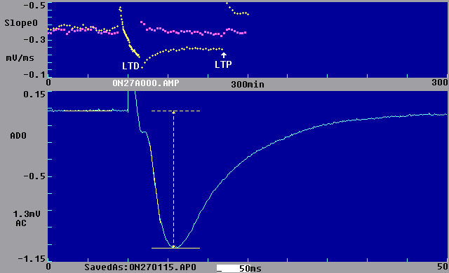
Fig. 1.4.1a shows the main page of the LTP Program illustrating the basic LTP experiment of slow alternating dual pathway stimulation, in this case using signal averaging. The bottom panel shows an extracellular synaptic response from the CA1 region of the hippocampus, averaged from four sweeps, and produced by single extracellular S0 stimulus pulses, 10 ms from the start of the sweep. Superimposed on the synaptic waveform are yellow lines to show where calculations were made for the S0 prestimulus baseline (left), slope (middle) and peak amplitude (right). The baseline, slope and peak amplitude 'calculation lines' are color-coded and are shown in yellow for an S0-evoked fEPSP and magenta for an S1-evoked fEPSP. The top panel in Fig. 1.4.1a shows calculations for slope produced by S0 stimulation (yellow crosses) and S1 stimulation (magenta squares).
Fig. 1.4.1. A
basic LTP/LTD experiment run by the LTP Program.
|
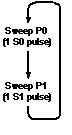
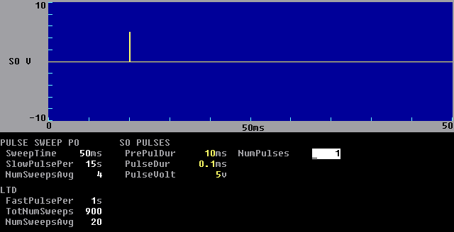
In the LTP Program, alternating dual pathway stimulation (S0 then S1) of the experiment in Fig. 1.4.1a is achieved by producing dual alternating sweeps (Pulse Sweep P0 then Pulse Sweep P1) in which Pulse Sweep P0 has one pathway stimulation by one extracellular electrode, S0 (Fig. 1.4.1c), and Pulse Sweep P1 has one pathway stimulation by extracellular electrode S1 (see Fig. 1.4.1b). The S0 and S1 stimulation outputs trigger stimulus isolation units that are connected to extracellular stimulation electrodes S0 and S1.
The LTP Program is actually capable of generating four different sweep stimulations with different stimulation capabilities on each. Two sweep stimulations are Pulse Sweeps P0 and P1, and these are usually used for single pulse stimulation, can be repeated at set time intervals, and the sweep data can be signal averaged. The other two sweep stimulations are Train Sweeps T0 and T1, and these are evoked as single, nonrepetitive sweeps that are usually used for train stimulation.
The induction of LTP by S0 stimulation (indicated by 'LTP' and up arrow below yellow crosses in the top panel of Fig 1.4.1a) is produced by evoking a single Train Sweep producing only 100 S0 pulses at 100 Hz (not shown). The induction of LTD by S0 stimulation (indicated by 'LTD' below yellow crosses in the top panel of Fig. 1.4.1a) is produced by rapidly repeating Pulse P0 Sweeps for a set number of times (900 here), once a second here. Since the Pulse P0 Sweep produces only 1 S0 pulse per sweep, this generates 900 S0 pulses at 1 Hz. (see the LTD stimulation fields in Fig. 1.4.1c).
Technical support can be obtained by contacting support at WinLTP Ltd.:
| Email: support@winltp.com |
or by directly contacting the author:
| Dr. William W. Anderson | |
| Dept. of Anatomy | |
| University of Bristol | |
| Bristol BS8 1TD, England | |
| Email: w.w.anderson@bristol.ac.uk | |
| Tel: 0117-928-7407 (from outside the UK dial +44-117-331-1968) |
I would like to thank my friends and colleagues for help with the testing of the LTP program, for both putting up with crashes, and rewriting your protocol files for yet another ("The Last" ha!) version. In particular, I would like to thank Caroline Delany, Vernon Clark, Steve Fitzjohn, Raj Mistry and Nicola Kemp for doing most of the debugging of this program, and Tim Benke for allowing me to use his exponential curve fitting C code.