- View sweeps by clicking on an Analysis
Graph data point - Impose single and averaged sweeps
- Quarantine bad sweeps in reanalysis
- PopSpike Area, Amplitude & Latency
- Three types of Slope measurement
- Analyze all EPSPs in a sweep
- Special analyses of trains Rs measurement from unfiltered trace
- Convert WinLTP data files to ABF files
- Reanalysis of ABF, IBW and WCP files
| Overview of WinLTP |
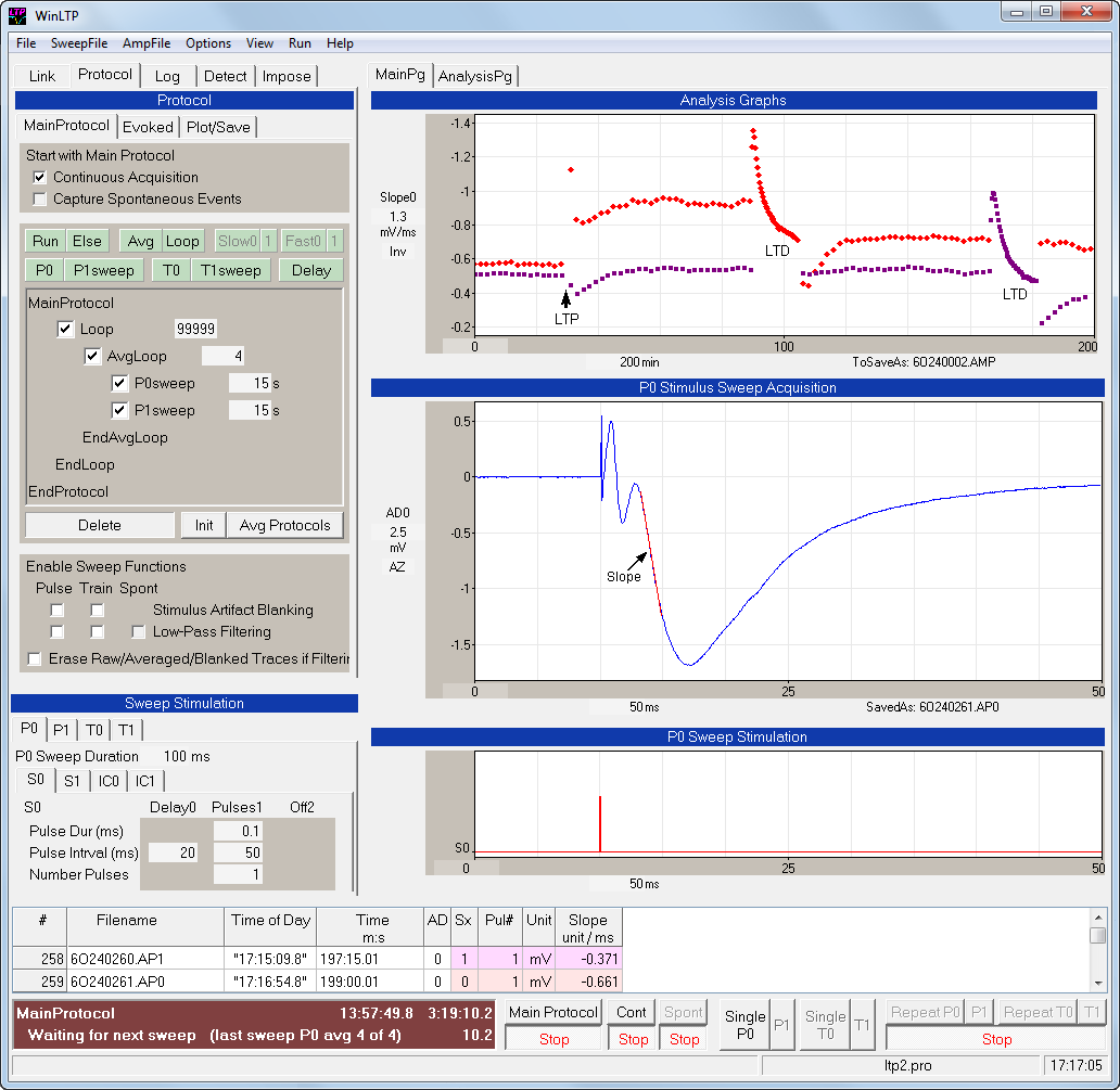
This figure shows the basic layout of the
WinLTP program showing Protocol fields (upper left panel), Analysis
graphs (one slope graph) (top right panel), Sweep Acquisition
(middle right panel), Sweep Stimulation fields and graphs (lower
left and right panels), and the Spreadsheet and Run Buttons (bottom
panels).
 |
|
Basic layout of the WinLTP Acquisition program.
Detection fields to change synaptic potential detection
values, as well as, the Imposing, Linking and Log tabsheets
are hidden behind the Protocol tabsheet. |
This figure shows a basic LTP experiment of
slow alternating dual pathway stimulation, in this case using signal
averaging. The right middle graph shows an extracellular synaptic
response from the CA1 region of the hippocampus, averaged from four
sweeps, and produced by single extracellular S0 stimulus pulses, 10
ms from the start of the sweep. Superimposed on the synaptic
waveform are red lines to show where calculations were made for the
S0 slope. The slope
'calculation lines' are color-coded and are shown in red for an
S0-evoked fEPSP and magenta for an S1-evoked fEPSP. The right top
graph shows calculations for slope produced by S0 stimulation (red
triangles) and S1 stimulation (magenta squares).
In WinLTP, alternating dual pathway
stimulation (S0 then S1) of the experiment is achieved by producing
dual alternating sweeps (Pulse P0sweep then Pulse P1sweep) in which
the P0sweep has one pathway stimulation by one extracellular
electrode, S0, and the P1sweep has one pathway stimulation by
extracellular electrode S1. The
MainProtocol panel shows the alternating P0sweep every 30 sec, then
P1sweep every 30 sec, in an AvgLoop of 4 to produce an average every
4 sweeps.
LTP induction by S0 stimulation (indicated by 'LTP' and up arrow below red triangles in the right top panel) is produced by by clicking the ‘Single T0’ Run Button to evoke a single Train Sweep of 100 S0 pulses at 100 Hz.
The induction of LTD by S0 stimulation
(indicated by 'LTD' below red triangles in the top panel) is
initiated by clicking the ’Repeat P0’ Run Button which produces
rapidly repeating Pulse P0sweeps for a set number of times (900
here), once a second here.
Of course, WinLTP functions are not limited to extracellular synaptic local field potential recording. It is also very good for patch-clamping, including being able to accurately sure series resistance from the unfiltered trace while measuring peak amplitude from the filtered trace.
The ability to multitask and perform stimulus/acquisition sweeps while at the same time record gap-free, continuous acquisition Axon Binary Files means that you can run mini acquisiton experiments by recording gap-free, continuous acquisition data (for later mini anaysis), while simultaneously assessing patch electrode viability and cell heath by measuring patch electrode series resistance and cell input resistance.
And with the Protocol Builder you can generate complex stimulation protocols like those for in-vitro kindling in epilepsy studies, or, when coupled with automated perfusion, enable running nearly fully automated experiments.
And the imposing of single and averaged sweeps enables careful visual examination of synaptic waveforms not only after, but also during, the experiment.