- View sweeps by clicking on an Analysis
Graph data point - Impose single and averaged sweeps
- Quarantine bad sweeps in reanalysis
- PopSpike Area, Amplitude & Latency
- Three types of Slope measurement
- Analyze all EPSPs in a sweep
- Special analyses of trains Rs measurement from unfiltered trace
- Convert WinLTP data files to ABF files
- Reanalysis of ABF, IBW and WCP files
| Slice Automated Perfusion Control |
Standard Slice Automated Perfusion Control
Fig. 3.1 shows an example of automated perfusion control in a slice experiment using the Slow0 Perfuse event in the Protocol Builder sequential script on the left in (B) by changing from Ch1 containing ACSF to Ch 2 containing a CaMKII Inhibitor. The labels of 'ACSF' for Ch1 and 'CaMKII Inhibitor' for Ch2 are set in (A). The entire stimulation sequence is started by unchecking the Continuous [99999] Loop checkbox (red arrow), and the researcher can leave at this time.
The bottom trace in (B) records the changing change of 1 digital bit which reflects changing from Ch1 to Ch2 and back to Ch1.
The output to the Experimental Log when this protocol was run clearly shows the time when perfusion was changed from Ch1 to Ch1 and what the solutions were ('ACSF' or 'CaMKII Inhibitor'), and what sweep immediately followed the perfusion change.
This example used the Standard perfusion where each reservoir went through a pinch-valve and on to the manifold (Fig. 3.2A). Pre-flushing was not used.
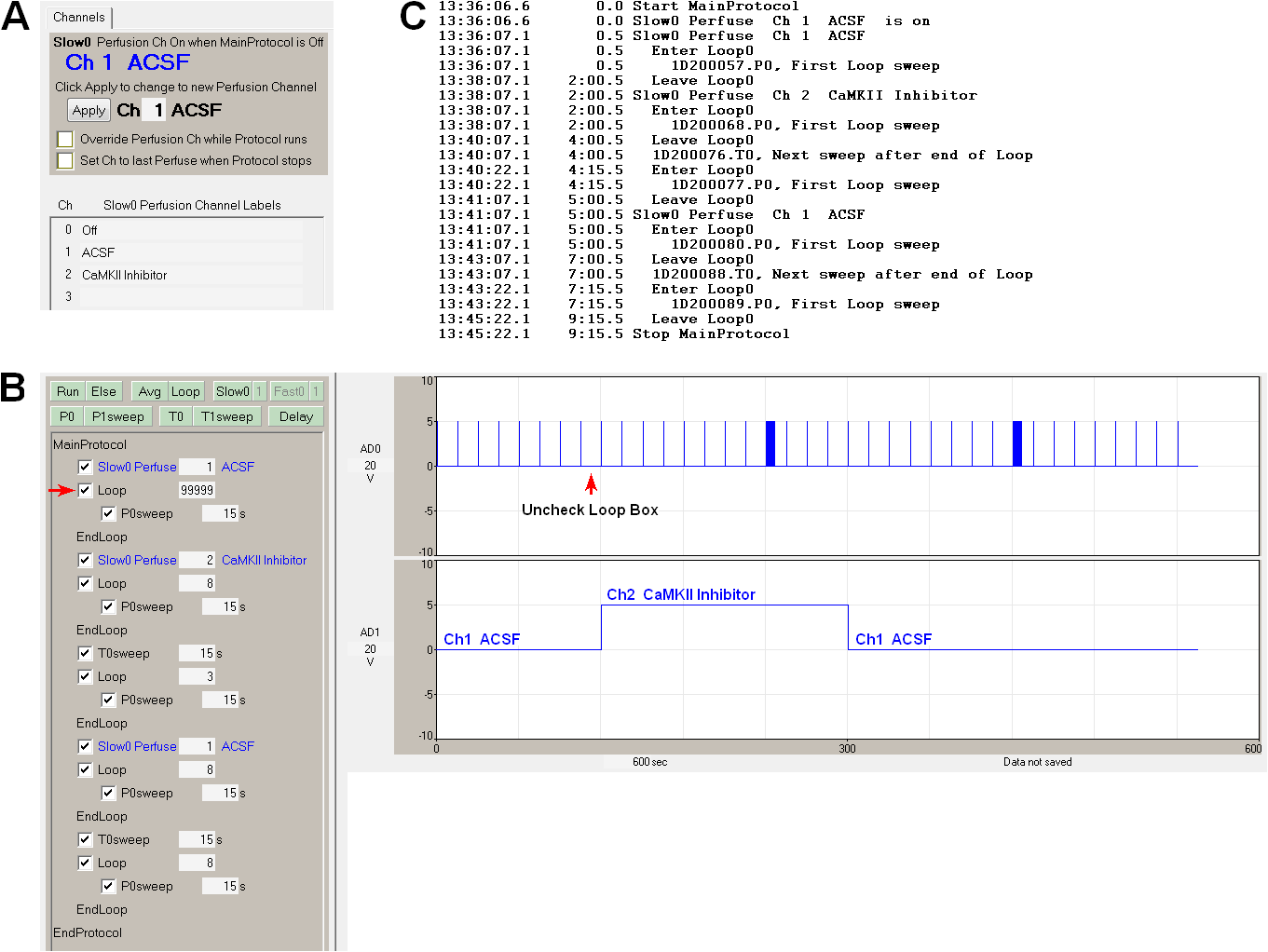 |
| Fig. 3.1. Sequential Protocol with Autmated Perfusion Control for an extracllular slice experiment. A) Setting the perfusion channel number and labels. B) A sequential script including Perfuse events to change perfusion solution between sweeps. The entire stimulation sequence is also started by unchecking the Continuous [99999] Loop checkbox (red arrow), and the researcher can leave at this time. The bottom trace records Bit1 of Port1 to indicate switching from Ch 1 to Ch 2 and back to Ch1 solutions. C) The experimental log output for this protocol. |
Slice Automated Perfusion Control with Pre-Flushing
If a 'T' junction is fitted in the perfusion line between the reservoir and the 'chamber' pinch valve, and a perfusion line off this 'T' juction goes through a second 'flush' pinch valve to a waste bottle, a pre-flush perfusion system is created (Fig. 3.2B). Then, if the flush valve on the perfusion line about to be switched to is opened before the chamber valve (Fig. 3.3B), then the stale, unoxygenated solution in perfusion line between the reservoir and the 'T' junction will be flushed out and replaced with oxygenated solution with the correct pH. Therefore, only roughly a 9 cm length of tubing between the 'T' junction and the manifold will still have the stale, unoxygneated (about 0.05 ml for 1/32" tubing) which will enter the chamber and bath the slice - the rest of the solution will be oxygenated with the correct pH.
See Section 10.2 in the on-line WinLTP Manual for more information on multi-slice automated perfusion control with pre-flushing.
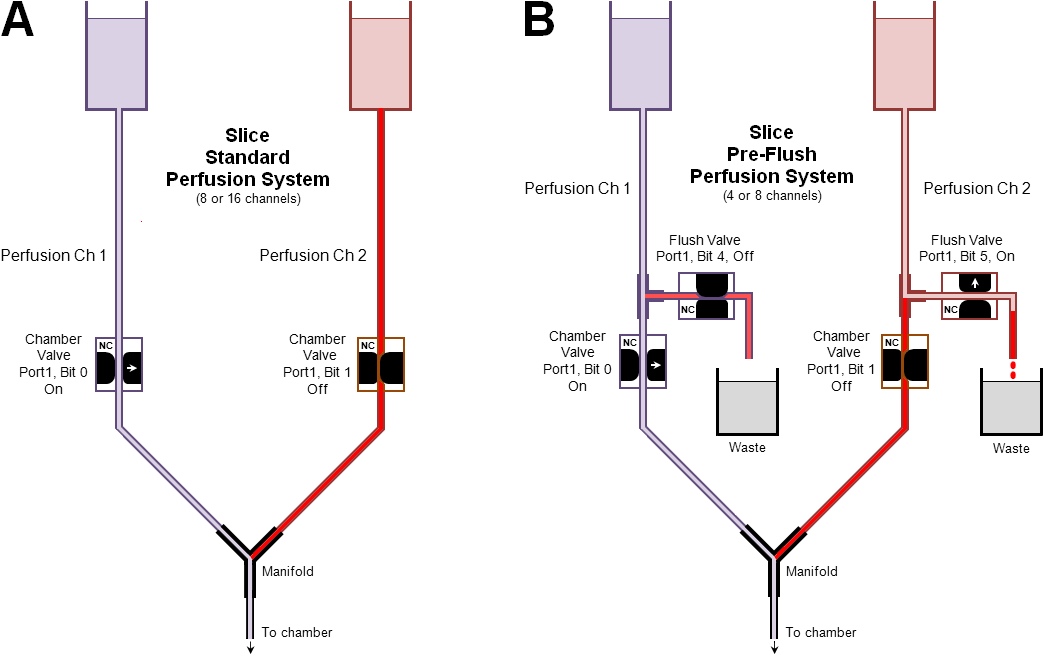 |
| Fig. 3.2. Standard and pre-flush slice perfusion systems. A) The slice standard perfusion system with 1 valve/line. B) Pre-flushing the next perfusion line to remove most of the stale, unoxygenated solution sitting in the line. The slice pre-flush perfusion system with 2 valves/line for a four line perfusion system. (The Flush Valve has been turned on for a sufficient time to clear the perfusion line from the reservoir to the T-fitting, but the Chamber Valve has not yet been turned on). The dead volumes for the two system lines are indicated in red. Basically the pre-flush system has a dead volume from the T-fitting to the manifold, which could be approximately 10 cm or less. The dead volume of the standard perfusion system could be anywhere from almost 0 cm to 1 meter depending on your configuration. |
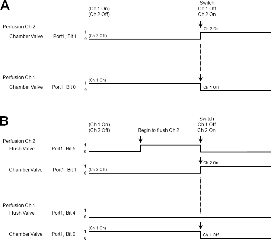 |
| Fig. 3.3. Switching from Ch 1 to Ch 2 using a Perfusion Controller set up (a) in a standard 8-channel configuration, and (b) in a pre-flush 4-channel configuration. Note how the Ch2 Flush Valve (Bit 5) turns on before the switch from Ch1 to Ch2 and then turns off at the switchover. |
Multi-slice Automated Perfusion Control
In addition to automated perfusion control using sequential protocol scripts, the other important capability of WinLTP to do automated multi-slice experiments is the ability to realistically Run Many WinLTP Programs at Once on One Computer. Because of the low cost of National Instruments boards and WinLTP Advanced Mode software, running many WinLTP's at once becomes feasible.
For more information see Section 10.2.8 in the on-line WinLTP Manual.